The battery cell manufacturing process divides broadly into three stages: electrode manufacturing, cell assembly, and formation (activation). For readers new to the sequence of secondary-battery production, this article lays out the flow from mixing to degassing and explains what form the patents attached to each step take and how process patents reach cells outside the factory.
① What’s the Topic
A cell is made in the order “electrode process → assembly process → formation process,” and patents attach at every node from coating to formation. In particular, a patent on a method of producing a product may extend to the sale and import of cells made by that method, so process patents cannot be treated merely as a “problem inside the factory.”
Start with the industry context. Lithium-ion batteries (LIBs) are made through a multi-stage process that runs through slurry mixing, coating, drying, calendering, slitting, vacuum drying, jelly roll fabrication (the internal cell structure formed by layering electrodes and separators), welding, packaging, electrolyte filling, formation, and aging, and the manufacturing processes are described as very similar even when the cell format differs—cylindrical, pouch, or prismatic[1]. The same review cites earlier work estimating that manufacturing accounts for about 25% of LIB cost[1].
The tension lies in the length of the process. Because there are many consecutive process steps and material properties, electrode compositions, and cell designs strongly affect the processes, transferring lab-scale results to production scale is itself cited as a challenge[2]. Words such as coater, notching, and formation that appear in equipment-order and plant-expansion news only make sense once you know which node of this long process they refer to. The same goes for patents: even among “battery patents,” how rights are enforced differs depending on which step is claimed and in what form (method, apparatus, or product). The question this article answers is this: In what order is a cell made, where and in what form do patents attach along that sequence, and how do process patents used inside the factory affect the cells that leave it?
② Basic Principle — Spread Batter on Foil, Roll It Up, and Break It In
The flow is easy to grasp if you compare cell making to kitchen work. You spread a batter (slurry) thinly on cooking foil (the current collector), dry it in an oven, press it with a rolling pin to set the thickness, and cut it to size. The cathode and anode sheets made this way are rolled up like gimbap (a Korean rice roll) or stacked layer by layer, alternating with a thin film (the separator), placed in a container (a can or pouch), and a sauce (the electrolyte) is poured in; then, much like breaking in new shoes, the cell is “broken in” with its first charge. Academic reviews likewise divide this flow into three parts: electrode preparation, cell assembly, and electrochemistry activation[1].
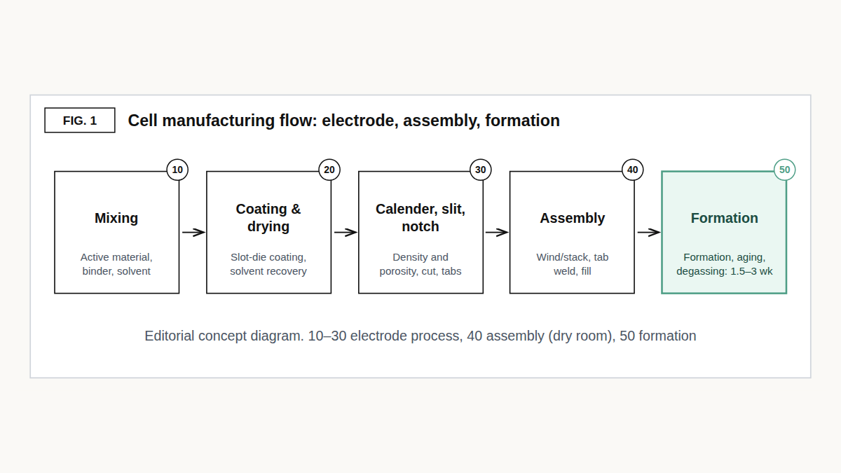
Source: editorial concept diagram based on Liu et al. (2021, iScience)
The electrode process begins with mixing. The active material (the main material that stores lithium), a conductive additive (an additive that helps electrons flow), and a binder (the glue that holds particles together) are mixed with a solvent into a uniform slurry; the cathode usually uses a PVDF binder in NMP solvent, and the anode uses an SBR binder and CMC in water[1]. Binder systems are covered further in the article on electrode binder chemistry, and dispersion quality in the article on slurry dispersion pressure.
The slurry passes through a slot die and is applied to both sides of the current collector (aluminum foil for the cathode, copper foil for the anode), after which the solvent evaporates in drying equipment[1]. NMP, the toxic cathode solvent, is recovered during drying and reused[1]. An example of a coating-equipment patent is in the analysis of the dual slot-die coater patent.
Next, calendering presses the electrode between rolls to set physical properties such as bonding, conductivity, density, and porosity[1]. Unwinding foil from a roll, processing it continuously, and rewinding it onto a roll—as in coating, calendering, and slitting—is called roll-to-roll (R2R) processing, and this segment runs at a high throughput of over 35 m per minute[1]. Slitting is the R2R process that cuts the calendered electrode to a set width; with conventional blades or chisels, edge defects such as burrs (rough protrusions left on the cut surface) can penetrate the separator and cause a short circuit, and laser cutting is also being studied[1].
Notching is the process of cutting the electrode edge to form tabs (the terminals through which current enters and leaves), and one laser-notching equipment patent claims a configuration that processes electrode tabs with a laser along tab-processing holes formed circumferentially in a cylindrical drum[3]. The design issues are covered in the laser-notching patent analysis. Finished electrodes have their residual moisture removed in a vacuum oven and their moisture content checked[1].
The assembly process takes place in a dry room with extremely low moisture[1]. That is because residual moisture reacting with the lithium salt in the electrolyte (LiPF6) can generate hydrogen fluoride (HF) gas, which damages materials and can cause safety problems[1]. The cathode, separator (a film that keeps the two electrodes apart while letting only ions pass), and anode are layered and either wound (winding) or stacked (stacking) to build the internal structure of the cell; the review describes stacking as typical for pouch cells and winding for cylindrical and prismatic cells[1].
The differences among these methods are compared in three ways to stack an electrode assembly. In winding, the tension on the material is also a quality variable, and a control method that compensates for tension changes caused by the rotational moment of inertia of idler rollers during periods when the line speed rises and falls is registered as a patent (KR101899991B1, Pito, filed 2016)[4]. Its claim boundary is covered in the patent that calculates even a winding roller’s inertia.
Next comes tab welding, which attaches an aluminum tab to the cathode and a copper tab to the anode. The most common method is ultrasonic welding, some manufacturers use resistance welding, and laser welding, though it performs better, has been assessed as suited for now to high-end products because of its cost[1]. There is also a patent on joining by ultrasonic bonding followed by laser welding[5], covered in the article on GM’s tab-welding patent. The electrode assembly is placed in an enclosure (a can or pouch) whose format differs by manufacturer, so there is no unified standard, and cell assembly ends with electrolyte filling before final sealing[1]. The layer structure of pouch enclosures continues in the article on pouch film, and the claim boundary of a filling-pressure patent in the analysis of the “atmospheric-pressure first” filling patent.
The formation (activation) process turns a freshly assembled cell into a usable one. First, to protect the copper current collector from corrosion, the cell is charged to a low voltage (e.g., 1.5 V) and then rested so the electrolyte soaks into the electrodes (wetting); it is then charged and discharged at a low current such as C/20 (a rate that fully charges the cell in 20 hours), with the current gradually increased, to build a stable SEI (solid electrolyte interface, a thin protective film formed as the electrolyte decomposes) on the anode surface[1].
This first charge and discharge is called formation. Gas generated during formation must be removed for safety, and after completing wetting and SEI stabilization on aging shelves, the cell goes through degassing, which removes gas once more before final sealing[1]. Aging is also needed to determine whether leakage currents are too high before the rated capacity is assigned[6]. Why the gas forms is explained in the article on formation and degassing.
③ Comparison — What Each Stage Makes, and Where Cost, Energy, and Time Go
| Item | Electrode process | Assembly process | Formation process |
|---|---|---|---|
| Main sub-steps | Mixing → coating and drying (solvent recovery) → calendering → slitting and notching → vacuum drying[1] | Winding or stacking → tab welding → packaging → electrolyte filling[1] | Low-voltage charge and wetting → formation (low-rate cycling) → aging → degassing[1] |
| What it produces | Cathodes and anodes cut to set widths[1] | Electrolyte-filled cell (before formation)[1] | Cell with its SEI formed and leakage current screened[1][6] |
| Key quality variables | Bonding, conductivity, density, porosity; cut-edge defects; residual moisture[1] | Dry-room moisture control; contact resistance and strength of tab welds[1] | Electrolyte wetting; SEI uniformity depending on formation current and temperature[1] |
| Typical equipment and location | Slot-die coater and dryer, calender rolls, slitter (blade or laser), vacuum oven[1] | Dry room, winding/stacking equipment, ultrasonic and resistance welders[1] | Charge-discharge (formation) equipment, aging shelves[1] |
| Share of manufacturing cost* | 38.95%[1] | 28.44%[1] | 32.61% (largest single step)[1] |
| Share of energy per cell* | 57.24% (drying and solvent recovery alone: 46.84%)[1] | 12.88%, plus the dry room at 29.37%[1] | 0.53%[1] |
| Time and speed | Mixing 30 min–5 h, vacuum drying 12–30 h[1] | Packaging depends on cell design (no figures given for stacking and welding)[1] | 1.5–3 weeks[1] (wetting and formation 3–7 days, plus up to 2 weeks of aging[6]) |
Source: reconstructed by the editorial team from Liu et al. (2021, iScience) and Wood et al. (2019, Joule)
What this table shows: Formation (formation and aging) uses only 0.53% of the energy per cell, yet as a single step it carries the largest share of cost (32.61%)[1] (the two figures come from sources based on different cells and facilities). Its cost comes not from electricity but from time of up to three weeks[1], from equipment, and from space of up to 25% of plant floor area[6]; energy, by contrast, is concentrated in electrode drying and solvent recovery (46.84%) and the dry room (29.37%)[1].
④ Patent Perspective — A Method Patent Follows the Cell Out of the Factory Gate
First, some terms. A claim is the part of a patent that states in sentences the scope of protection sought, and the Korean Patent Act determines the scope of protection of a patented invention by what is written in the claims (Article 97)[7]. By form, claims divide into product, method, and apparatus (equipment) claims, and process technology can be claimed in the form of “a method comprising the steps of ….”
“Working” a method invention means using the method or offering its use, but for an invention of a method of producing a product, working also includes using, transferring, leasing, exporting, or importing the product produced by that method, or offering to transfer or lease it (Korean Patent Act, Article 2, item 3(b) and (c))[7]. The United States likewise makes anyone who, without authority, imports into the United States, or sells or uses within it, a product made by a process patented in the United States liable as an infringer (35 U.S.C. §271(g)).
However, a product is no longer considered made by that process after it is materially changed by subsequent processes or becomes a trivial and nonessential component of another product[8].
The problem is proof. Because a method is worked inside the factory, it is hard for a right holder to look into a counterpart’s process. Article 129 of the Korean Patent Act presumes that, where a method of producing a product is patented, an identical product was produced by the patented method, but it does not apply this presumption to a product that was publicly known or publicly worked in Korea before the patent application was filed, or that was disclosed in a publication or made available through a telecommunication line[7].
For widely known products such as electrodes or cells, this proviso is likely to keep the presumption from operating. Under U.S. §295, if the court finds a substantial likelihood that the product was made by the patented process and that the right holder made a reasonable effort to determine the process actually used but could not, the product is presumed to have been so made and the burden of proof shifts to the other party[9].
Korea also has Article 126-2, which requires a party that denies the specific content, manner, and form of the infringing conduct alleged by the right holder to present the specific content, manner, and form of its own conduct, and court orders to submit materials (Article 132)[7]. In addition, producing or transferring as a business an article used only for working a patented method is deemed infringement (Article 127, item 2)[7]. This means equipment suppliers may not be unaffected by process patents either.
Reopening on Google Patents the eight patents this site has analyzed step by step and checking the form of claim 1, we found six method claims, one apparatus claim (a laser-notching system, KR102430493B1)[3], and one product claim (the low-tortuosity electrode of MIT and others, US9065093B2)[10]. The sample is too small to generalize from, but the method form is in the majority. US9065093B2, the product-claim example, claims the electrode itself through measurable values—pores with a tortuosity (a value describing how winding the ion path is) below 1.5 and pores of 2 or more, and a total porosity of 20–60%[10]. Such a claim leaves room for comparison by analyzing a finished electrode. How this electrode structure connects to calendering density is covered in the article on calendering density.
What beginners should be especially careful about is gauging the scope of rights from the title or abstract alone. The abstract of LG Energy Solution’s US2025/0375790A1 describes an apparatus, a coater, but all of its claims are “coating methods using that coater”[11]. This application is a divisional of US12420303B2, which claims the coater itself and was granted in 2025, and the condition attached to the parent’s claim 1—“the thinner die lip is 800 μm or more”—is absent from the divisional’s claim 1[12][11].
SK On’s dry-electrode-sheet patent contained method, apparatus, and electrode claims at the publication stage (US2023/0378422A1), with a compression ratio of 0.10–0.65[13], but the granted US12199265B2 (2025) was narrowed to 10 claims, all method claims (with two independent claims, 1 and 10), its compression ratio narrowed to 0.10–0.27, and the roll-speed conditions from the dependent claims moved into the independent claims. Even so, the title of the granted patent still contains “apparatus” and “electrode,” and its abstract still states 0.10–0.65[14]. How it was narrowed should be checked in the article on SK On’s dry-electrode compression-ratio patent and in the prosecution history.
| Process step | Patent · applicant · status | Claim 1 category | Gist of claim 1 (restated) | Clue to look for in the finished product (editorial judgment) |
|---|---|---|---|---|
| Coating | US2025/0375790A1 · LG Energy Solution · published 2025, pending | Method | Forming a slurry layer with a dual slot-die coater whose lower die lip is thicker than the intermediate and upper die lips[11] | Internal equipment structure, hard to confirm from the finished electrode |
| Calendering (dry electrode) | US12199265B2 · SK On · granted 2025, Active | Method | Two-stage calendering with three rolls, compression ratio (W1−W2)/W1 of 0.10–0.27, roll speeds V1<V2<V3, etc.[14] | Process conditions, hard to trace back from the sheet |
| Notching | KR102430493B1 · DA Technology · granted 2022, Active | Apparatus | Laser irradiator, jig base, cylindrical pattern jig with tab-processing holes, rotation unit, suction pipe, etc.[3] | The equipment structure can be compared directly |
| Tab welding | US11710879B2 · GM · granted 2023, Active | Method | First joining the foil stack to create a joining region, then forming the tab’s second weld joint within that region[5] | Tearing down a cell may allow the weld position to be observed |
| Electrolyte filling | US10476097B2 · filed by NEC Energy Devices (now Envision AESC) · granted 2019, Active | Method | Starting electrolyte injection at atmospheric pressure, then performing injection and pressure reduction intermittently and alternately[15] | The pressure history hardly leaves a trace in the finished cell |
| Formation | US12456749B2 · LG Energy Solution · granted 2025, Active | Method | Steps of electrolyte injection, pressurized initial charge and discharge, vacuum exposure, second pressing, aging, and degassing, with a second pressure of 0.5–3 kgf/cm² and 2<P1/P2<10[16] | Hard to confirm without process records |
Source: reconstructed by the editorial team from each patent publication on Google Patents and USPTO grant publications (claims of US10476097B2 and US12456749B2 cross-checked)
In short, the effect of a process patent can follow the cell out of the factory gate. Because “working” an invention of a production method includes transferring and importing the product, process-patent risk should be judged not only by “where it was made” but also by “where it is sold.” However, since Korea’s presumption of the production method is likely not to operate for common products, actual enforceability may depend heavily on whether the claim elements leave a trace in the finished cell.[7][8]
Design-around scenario (with counterarguments). The first design-around one might consider is moving process conditions outside the claimed scope—for example, starting electrolyte filling under reduced pressure rather than atmospheric pressure[15], setting the first-to-second pressing ratio in formation outside 2–10[16], or placing part of the second weld outside the first joining region[5]. Literally, this may fall outside the scope of rights, but there are counterarguments. First, if the difference only yields substantially the same function and effect, a risk of infringement may remain under the doctrine of equivalents (the principle that treats something as infringing if it is substantially the same, even though it differs from the claim language).
Second, moving production abroad may not be enough, because importing or selling cells made by that method in Korea or the United States may constitute working or infringement[7][8]. Third, if the claimed numerical range is also the window in which quality is secured, a design-around that steps outside it may come back as yield and quality losses. Conversely, on the right holder’s side, the further upstream the process patent, the more processes lie between the freshly coated electrode and the finished cell, so the “materially changed” exception of §271(g) may become a point of dispute[8].
⑤ Limits and Outlook
Optimistically, the process is moving toward becoming shorter. Solvent-free processing has emerged as a way to skip the drying step and avoid organic solvents, and Tesla acquired Maxwell Technologies in 2019 and made dry-electrode manufacturing technology part of its future battery production plan[1]. Research on fast formation that narrows the voltage window or raises the current also continues, and one protocol was reported to cut the formation of NMC/graphite pouch cells to about 14 hours, 8.5 times faster than the conventional method[1]. If drying and solvent recovery, which use 46.84% of the energy, and formation and aging, which account for 32.61% of the cost, shrink, the process map itself could change[1].
Counter-scenario: New processes can become new patent-dense zones. As in the SK On case above, dry electrodes already have an example of rights set in units of narrow conditions such as roll-gap ratio and speed ratio[14], and there is also an assessment that most solvent-free methods face uniformity and scale-up challenges[1]. How much of the benefit of a shorter process will be realized in mass production, and who has already tied up those chokepoints with rights, remains uncertain. Related issues continue in the article on dry-electrode process patents and the article on PTFE fibrillation.
Strategic alternative: Build an “IP process map” that overlays key patents on the process flow chart. Putting on one page the claim form of the patents at each node (method, apparatus, or product), their numerical ranges, the traces they leave in the finished product, and the countries where the product is sold lets equipment introduction, process changes, and export plans be reviewed together from the standpoint of freedom to operate (FTO, the judgment of whether making and selling a product infringes others’ patents). Inspection technology that looks inside cells nondestructively is covered in the article on radiographic total inspection.
Action to check (planning/IP teams): When listing the patents attached to each node of your process flow chart, check the claim 1 form and numerical ranges directly in the granted publication—not the title, abstract, or published-application claims—and mark, for each country where the cell is sold or imported, whether the rights remain in force.
Items Requiring Verification
- How the proviso of Article 129 of the Korean Patent Act (products publicly known or worked before filing, etc.) applies to individual electrode or cell process patents requires case-by-case assessment; the statement that the presumption is “likely not to operate” is a general reading of the statutory text.
- The requirements for the doctrine of equivalents (Korean Supreme Court and U.S. case law) are treated only in general terms; the original judgments were not reviewed for this article.
- How the “materially changed” exception of 35 U.S.C. §271(g) would be judged between an upstream electrode process patent and a finished cell or pack requires a review of case law.
- The reasons US12199265B2 was narrowed from the published application (US2023/0378422A1), such as rejections and amendments, were not checked in the prosecution history.
- The divisional application US2025/0375790A1 is still pending, so whether it is granted and its final claim scope may change.
- In Table 1 of Liu et al. (2021), the cost shares are estimates from the 2019 BatPac model (67 Ah NMC622/graphite cell, a plant making 100,000 EV packs a year), while the energy shares are measurements by Yuan et al. (2017), cited in the same table, for 32 Ah LMO/graphite cell production at a pilot-scale facility, so the two rest on different bases. The text gives the formation/aging cost share as 32.16% and 32%, while Table 1 gives 32.61% (the Table 1 column sum confirms 32.61%); values may differ for current plants and cell formats.
- The legal status (Active/Pending) and terms of each patent are as displayed on Google Patents; the latest status, including annuity payments and assignments, should be checked in each patent office register.
- The assembly method by cell format (pouch = stacking, cylindrical/prismatic = winding) follows the summary in Liu et al. (2021); actual practice may differ by manufacturer and product.
Sources
- Liu, Y., Zhang, R., Wang, J., Wang, Y., “Current and future lithium-ion battery manufacturing,” iScience 24(4), 102332, 2021 (full text read via Europe PMC, PMC8050716) (accessed 2026-09-25). Link
- Kwade, A., Haselrieder, W., Leithoff, R., Modlinger, A., Dietrich, F., Droeder, K., “Current status and challenges for automotive battery production technologies,” Nature Energy 3, 290–300, 2018 (abstract) (accessed 2026-09-25). Link
- DA Technology Co., Ltd., KR102430493B1, “Laser Notching System for Manufacturing Secondary Battery,” granted Aug. 10, 2022, Google Patents (accessed 2026-09-25). Link
- Pito Co., Ltd., KR101899991B1, “The tension control method for manufacturing apparatus of rechargeable battery,” granted Sep. 18, 2018, Google Patents (accessed 2026-09-25). Link
- GM Global Technology Operations LLC, US11710879B2, “Method and apparatus for welding foils,” granted Jul. 25, 2023, Google Patents (accessed 2026-09-25). Link
- Wood, D. L., Li, J., An, S. J., “Formation Challenges of Lithium-Ion Battery Manufacturing,” Joule 3(12), 2884–2888, 2019 (abstract on ORNL publication page) (accessed 2026-09-25). Link
- Korea Ministry of Government Legislation, National Law Information Center, “Patent Act” (Act No. 21134, effective Nov. 11, 2025), Articles 2, 97, 126-2, 127, 129 and 132 (accessed 2026-09-25). Link
- Legal Information Institute (Cornell Law School), “35 U.S. Code § 271 – Infringement of patent” (accessed 2026-09-25). Link
- Legal Information Institute (Cornell Law School), “35 U.S. Code § 295 – Presumption: Product made by patented process” (accessed 2026-09-25). Link
- Massachusetts Institute of Technology et al., US9065093B2, “Controlled porosity in electrodes,” granted Jun. 23, 2015, Google Patents (accessed 2026-09-25). Link
- LG Energy Solution, US20250375790A1, “Dual Slot Die Coater and Method for Coating Electrode Active Material Slurry Using the Same,” published Dec. 11, 2025, Google Patents (accessed 2026-09-25). Link
- LG Energy Solution, US12420303B2, “Dual slot die coater and method for coating electrode active material slurry using the same,” granted Sep. 23, 2025, Google Patents (accessed 2026-09-25). Link
- SK On, US20230378422A1 (published application of US12199265B2), published Nov. 23, 2023, Google Patents (accessed 2026-09-25). Link
- SK On, US12199265B2, “Method and apparatus for preparing dry electrode sheet for secondary battery, dry electrode sheet for secondary battery, electrode for secondary battery and secondary battery,” granted Jan. 14, 2025, Google Patents (accessed 2026-09-25). Link
- NEC Energy Devices (now Envision AESC Energy Devices), US10476097B2, “Method of manufacturing secondary battery and apparatus for the same,” granted Nov. 12, 2019, Google Patents (cross-checked with the USPTO grant publication) (accessed 2026-09-25). Link
- LG Energy Solution, US12456749B2, “Battery cell activation method and battery cell manufacturing method comprising same,” granted Oct. 28, 2025, Google Patents (cross-checked with the USPTO grant publication) (accessed 2026-09-25). Link
This article is a technology and patent trend commentary, not legal advice. Specific FTO judgments require professional review.
Related Reading
- Three Ways to Stack an Electrode Assembly — Winding, Stack & Folding, and Lamination & Stacking
- How Calendering Density Reroutes Ions — Electrode Porosity, Tortuosity, and MIT’s Low-Tortuosity Electrode Patent (US9065093B2)
- Why Cells Release Gas on First Charge — Electrolyte Decomposition Mechanisms and the Patent Boundary of Formation and Degassing
FRONTIERCELL PRIMER · 2026.09
More from this primer series
- How to Read a Battery Spec Sheet — What Wh, Ah, Wh/kg, C-rate, and SOH Tell You, and What They Don’t
- What’s the Difference Between A1 and B2 After a Patent Number? — A Primer on Reading Battery Patents Through Publication, Grant, and Expiry
- ITC Complaints, Invalidation Trials, Settlements — The Terms You Need to Read Battery Patent Dispute News