A lithium-ion cell releases gas the moment it is first charged, as part of the electrolyte decomposes. This article explains where that gas comes from and what it is, and why the degassing process that removes gas after formation is contested in patents down to ‘the ratio of pressures.’
① What’s the Topic
Degassing is less a process of ‘removing gas’ than a process of ‘how little electrolyte is lost along with the gas.’ And because gas escapes more slowly as cells get larger, the larger the cell, the more this process design governs both quality and production speed.
Start with the industry situation. An assembled cell is not shipped immediately. In the formation process, where the cell is charged and discharged for the first time after electrolyte injection, a protective film called the solid electrolyte interphase (SEI) forms on the anode surface, and in the process reductive decomposition of the electrolyte generates gas[2]. Pouch cells keep a gas pocket to collect this gas, remove it by degassing, and then seal.
The tension lies in scale and speed. A 2024 study comparing a coin cell (0.72 mAh) and a large-format automotive cell (72 Ah) under the same conditions reported that the composition and amount of gas were highly comparable, but that the gas release rate was lower in the larger cell, likely limited by bubble transport through the electrode stack[1]. On mass-production floors that must cut formation time and cost, slow gas release is a process bottleneck.
So the question this article seeks to answer is this: From what reactions and in what forms does gas arise inside a cell, how does degassing remove it, and where in that process do patents put up fences?
② Basic Principle — The First Rise of Bread Dough and ‘Punching Down’
A baking analogy makes this easy to understand. When dough first ferments, yeast makes it grow while releasing gas. The ‘growth’ of the SEI during formation is similar. On the anode surface, electrolyte solvents such as ethylene carbonate (EC) accept electrons and decompose, leaving behind components of the protective film and releasing gas as a by-product. Fermented dough is pressed by hand to release the gas, but pressing too hard ruins its moisture and texture. Degassing is the same: only the gas should be removed, while as much electrolyte as possible stays inside the cell.
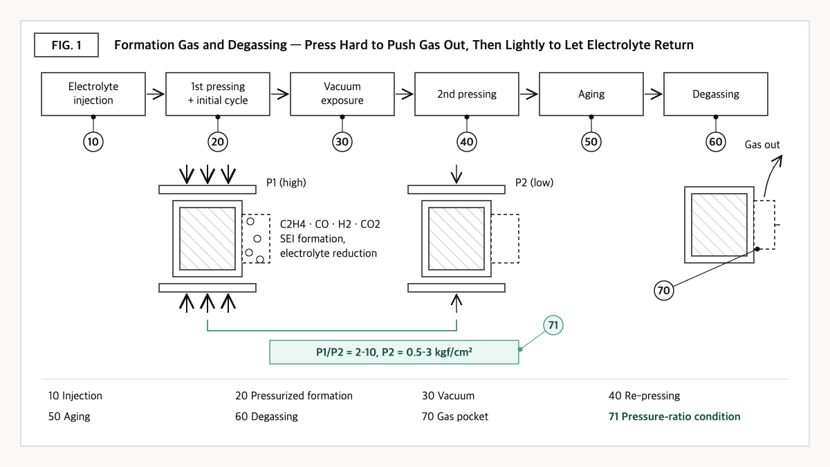
Source: reconstructed by the editorial team from Scharf et al. (2024) and the claim structure of US12456749B2.
The type of gas is a fingerprint of the reaction pathway. According to a study measuring formation gas from NMC811/graphite cells by online electrochemical mass spectrometry (OEMS), the gases produced by SEI formation and electrolyte reduction were mainly ethylene (C2H4), followed by carbon monoxide (CO) and hydrogen (H2)[1]. Residual trace water in the cell is assumed to be the primary source of hydrogen, and hydrofluoric acid (HF), formed when moisture reacts with the lithium salt, is reduced earlier at about 2.2 V (vs. Li+/Li)[1]. Carbon dioxide (CO2) evolved from the very start of charging as lithium carbonate residues on the cathode surface dissolved, and was later consumed at the negative electrode[1].
Temperature is also a variable. In the same study, formation at 10°C produced gas for up to 120 minutes after charging began, whereas at 40°C that span nearly halved to about 60 minutes[1]. In exchange, total gas per gram of graphite rose from 40.1 μmol at 10°C to 51.3 μmol at 25°C and 59.8 μmol at 40°C[1]. Raising the temperature speeds up formation but produces more gas — a trade-off. Gas can also arise after formation. At higher voltages, electrolyte oxidation can be the main contributor to gas evolution, and NMC cathodes begin releasing oxygen from a state of charge (SOC) of about 80%, which can trigger chemical oxidation of the electrolyte[2]. Volume changes caused by gas can alter stack pressure and impair electrode contact[2].
③ Comparison — Types and Sources of Formation Gas
| Gas | Main cause | Share in coin cell (25°C) | Share in 72 Ah large cell (25°C) |
|---|---|---|---|
| Ethylene (C2H4) | SEI formation and electrolyte reduction[1] | ≈77%[1] | ≈71%[1] |
| Carbon monoxide (CO) | SEI formation and electrolyte reduction[1] | ≈19%[1] | ≈16%[1] |
| Hydrogen (H2) | Reduction of residual water assumed to be the main source; HF reduced at about 2.2 V (vs. Li+/Li)[1] | ≈4%[1] | ≈14%[1] |
| Carbon dioxide (CO2) | Evolves early from dissolution of Li2CO3 residues on the cathode, later consumed at the anode[1] / electrolyte oxidation at high voltage[2] | Not given as a share figure in the study | |
Source: reconstructed by the editorial team from Scharf et al. (2024)[1] and Rowden and Garcia-Araez (2020)[2].
What this table shows: More than 70% of formation gas is ethylene[1], but it is worth noting that the hydrogen share grew from about 4% to about 14% in the large cell[1]. Given that residual water is assumed to be the main source of hydrogen[1], drying and moisture control may show up more sensitively in gas composition as cells get larger.
④ Patent Perspective — Claiming Not the ‘Magnitude’ but the ‘Ratio’ of Pressure
Because formation and degassing are combinations of equipment and process conditions, rights are often defined by ‘sequence’ and ‘numerical conditions.’ LG Energy Solution’s US12456749B2 is a good example. Priority date 2020-11-16 (Korean application KR10-2020-0152525), filing date 2021-11-04, grant date 2025-10-28, current assignee LG Energy Solution, legal status Active (adjusted expiration expected 2043-05-30), with 10 granted claims. The publication number is US20230049301A1, and KR102900629B1, WO2022103076A1, EP4064400B1, and CN114930590A are recorded as the same family[3]. The specification presents as its problem that gas trapped between the electrodes and the separator is hard to remove by conventional degassing, and that pressing hard to remove as much gas as possible discharges excessive electrolyte, which then takes a long time to be reabsorbed[3]. Restated element by element, claim 1 reads as follows.
| Elements of claim 1 (restated) | Meaning for the scope of rights |
|---|---|
| (a) Injecting electrolyte into the cell case | A conventional process step |
| (b) A first pressing step performing initial charge and discharge while the cell is pressurized | Pressurized formation — charge/discharge under pressure is required |
| (c) Exposing the cell to a vacuum condition | The existence of a vacuum step itself is required |
| (d) A second pressing step pressing the cell again, followed by an aging step | Two-stage pressing structure |
| (e) A degassing step removing the cell’s internal gas | Final gas removal |
| (f) The average second-pressing pressure P2 is lower than the first-pressing pressure P1 and within 0.5–3 kgf/cm² | Absolute-range limitation on second-pressing pressure |
| (g) The ratio of first to second average pressures P1/P2 is 2 or more and 10 or less | A limitation fixing the ‘ratio’ of pressures between the two pressing stages — the baseline for infringement judgment |
Source: reconstructed by the editorial team from the bibliographic data and claim structure of US12456749B2 on Google Patents (original claim language and drawings not reproduced verbatim).
The axis of the scope of rights is (g). The design concept — press hard in the first stage to push gas out of the stack, then press lightly in the second stage to aid electrolyte reabsorption — is compressed into a single figure: the ‘ratio.’ Based on this, design-around scenarios that could be examined include (i) equalizing the two stage pressures or keeping the ratio below 2, (ii) performing the second pressing outside 0.5–3 kgf/cm², and (iii) omitting the vacuum-exposure step or the second pressing step and inducing gas movement by other means (e.g., changing cell orientation or gas-pocket placement).
The counterarguments are clear. (i) and (ii) risk returning to the electrolyte-loss or residual-gas problems noted in the specification, and near the ratio boundary the judgment may depend on how ‘average pressure’ was measured. Whether the claims of the Korean, European, and Chinese family members have the same scope as the US patent also requires separate confirmation. As a cross-check of similar patents, there is LG Energy Solution’s own US11539068B2 (priority date 2017-12-15, filing date 2018-12-07, grant date 2022-12-27, Active). According to its specification, it places the gas pocket portion horizontally on a support block while tilting the battery body, allowing gas to be discharged easily while reducing the electrolyte discharged along with it[4]. This reads as the same applicant securing rights to the electrolyte-loss problem of degassing along different axes: ‘pressure profile’ and ‘cell orientation.’
⑤ Limits and Outlook
On the optimistic side, there is clearly room to shorten formation time through process-condition optimization, as shown by the result that raising the formation temperature nearly halves the gas-evolution span[1]. Degassing designs combining pressurization, vacuum, and re-pressurization are also likely to evolve toward compensating for bubble-transport limits in large cells.
There is also a counter-scenario. Speeding up formation by raising temperature actually increases the total amount of gas. The result that gas per gram of graphite increased from 40.1 μmol to 59.8 μmol at 40°C versus 10°C[1] shows that time savings can come back as a heavier degassing burden. Since gas release itself is slow in large cells[1], the risk of gas remaining inside the stack after a shortened formation may grow as well.
The strategic alternative is to develop formation conditions (temperature, current) and degassing conditions (pressure profile, vacuum, cell orientation) as one recipe, and to check FTO at the level of that recipe. Changing individual conditions alone may unexpectedly run into competitors’ ratio or sequence claims, while designing the whole recipe also creates room for securing one’s own rights.
Action to check (planning/IP teams): Summarize on one page the step sequence of your activation process (injection → pressurized charge/discharge → vacuum → re-pressing → aging → degassing) and the average pressure of each step, and check whether the P1/P2 ratio and the absolute P2 value fall within the ranges of claim 1 of US12456749B2 (2–10, 0.5–3 kgf/cm²).
Items Requiring Verification
- The claim scope and maintenance status of the Korean (KR102900629B1), European (EP4064400B1), and Chinese (CN114930590A) family members of US12456749B2 were not separately checked in this article.
- For US11539068B2, only the bibliographic data and the gist of the specification were checked; the specific wording of granted claim 1 was not verified in this article.
- The gas composition shares in this article are measurements from a single study on NMC811/graphite cells; figures for other chemistries (such as LFP) or electrolyte compositions were not checked.
Sources
- Janik Scharf et al., “Gas evolution in large-format automotive lithium-ion battery during formation: Effect of cell size and temperature,” Journal of Power Sources 603, 2024. Link
- Ben Rowden, Nuria Garcia-Araez, “A review of gas evolution in lithium ion batteries,” Energy Reports 6 (Suppl. 5), 10–18, 2020. Link
- Google Patents, US12456749B2 “Battery cell activation method and battery cell manufacturing method comprising same,” bibliographic data, family, and claim 1 (original checked 2026-09-23). Link
- Google Patents, US11539068B2 “Method for manufacturing secondary battery,” bibliographic data and gist of specification (checked 2026-09-23). Link
This article is a technology and patent trend commentary, not legal advice. Specific FTO judgments require professional review.
Related Reading
- Why Do Pouch Cells Seem to Swell So Much? — The Structural Reason for Swelling
- [Patent Analysis] Filling Electrolyte ‘Atmospheric-Pressure First,’ Not ‘Vacuum First’ — The Claim Boundary of the Reduced-Pressure Cycle Drawn by US10476097B2
- Electrolyte, From Liquid to Solid — The Safety-vs-Interfacial-Resistance Tradeoff