Internal short circuits in a cell are more likely to start at the edge of an electrode than at its center, especially at the boundary where the positive electrode coating ends. This article explains why covering that boundary with an insulating layer containing ceramic particles is needed, and where patents have put up their fences.
① What’s the Topic
The “boundary between the coated and uncoated portions” of the positive electrode is where short-circuit risk concentrates in a cell. That is why designs covering this boundary with an insulating layer of inorganic (ceramic) particles and binder are widely considered, and the focus of recent patent competition is shifting from “whether to cover it” to “how well it stays attached in electrolyte.”
Start with the industry context. In the race to raise energy density, electrodes are getting thicker, separators thinner, and coating and notching (the process of cutting the electrode into tab shapes) faster. All of these reduce the “margin” inside the cell.
The source of tension lies in the structure of the boundary. The positive electrode is made by coating active material onto an aluminum current collector while leaving the part that will become the tab uncoated. This remaining part is called the uncoated portion. Where the coating ends, a zone forms in which the active material layer gradually thins, and the aluminum of the uncoated portion faces the negative electrode across a single separator. Configurations that attach insulating tape at the boundary where the uncoated portion faces the negative active material layer in wound cells, to prevent short-circuit hazards, have long been filed as patents[3]. The problem is that insulating members sit immersed in electrolyte for the entire life of the cell. Recent patents cite as background that when an insulating layer wetted by electrolyte loses adhesion, it may lift or peel off[1].
So the question this article answers is: why do short circuits start at the electrode edge, how does a ceramic insulating layer guard that boundary, and where does the scope of patent rights lie?
② Basic Principle — The Corner Guard on a Wall
Picture a painted wall. The paint chips first not on the broad wall surface but at the corners. The line left after removing masking tape has thin paint and a step, so it is easily exposed when bumped. That is why corner guards are added. The coating boundary of an electrode is the same. The sliding zone, where the active material layer thins as it ends, and the exposed aluminum uncoated portion right next to it correspond to the “wall corner.”
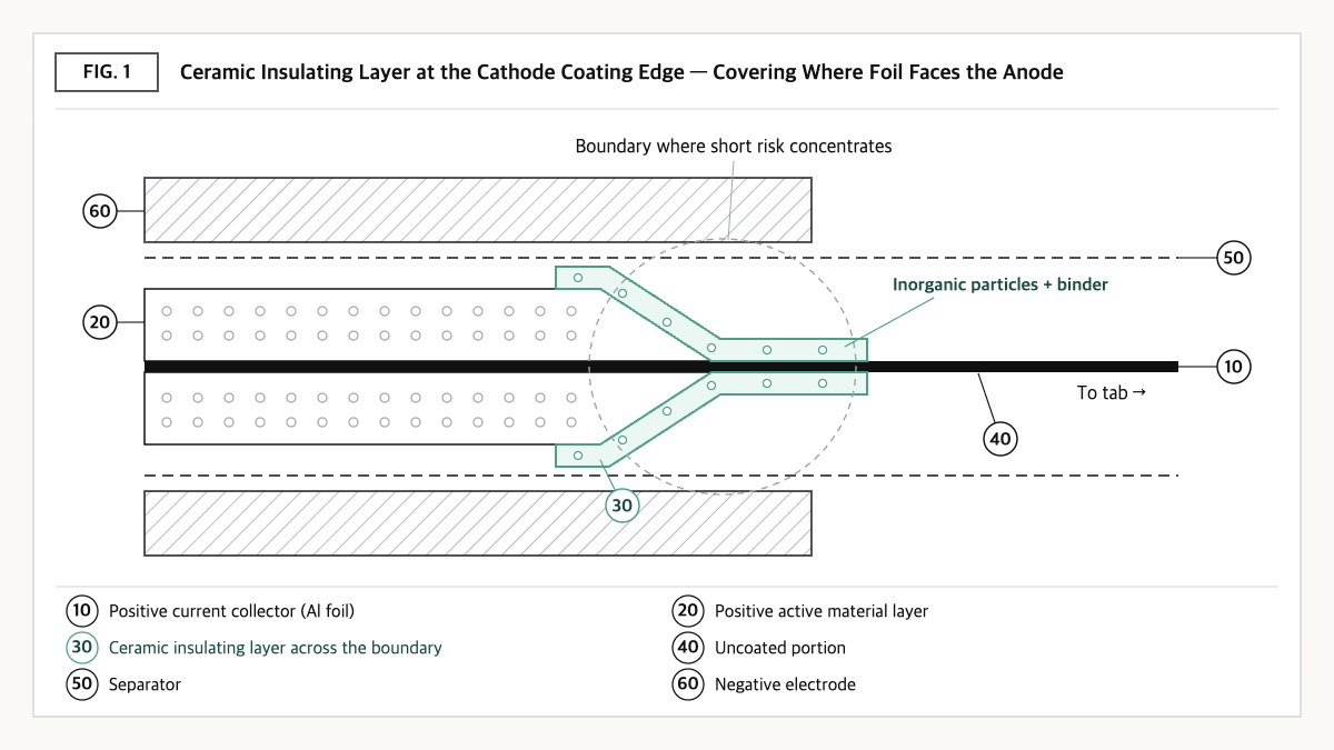
Source: reconstructed by the editorial team from the specifications of US12586794B2, KR20230019035A, and WO2009128605A2.
The paths by which short circuits start at this corner can broadly be grouped into three. First, when the cell heats up and the separator shrinks, the aluminum uncoated portion and the negative electrode come closer directly. Second, metal burrs or foreign particles from notching or slitting may pierce the separator. Third, active material particles detached from the coating boundary may lodge in gaps. In every case, an “insulator covering the boundary” provides one more layer of protection against direct contact between aluminum and the negative electrode.
A ceramic insulating layer makes this corner guard as a coating. Inorganic particles such as boehmite (AlOOH) or alumina (Al2O3) are mixed with a binder and applied across the boundary, from part of the uncoated portion to part of the active material layer[1][2]. The inorganic particles act as an electrically insulating, heat-resistant skeleton, and the binder acts as the glue holding particles to each other and to the electrode. If the binder swells in electrolyte and loses adhesion, the result is a corner guard that has a skeleton but falls off the wall.
This article’s perspective: the success of an insulating layer depends less on “how well it blocks” than on “how long it stays attached in electrolyte.” An insulating layer spends the cell’s whole life not dry but wet.
③ Comparison — Three Ways to Insulate the Boundary
| Method | Representative materials | Thickness (range stated in literature) | Formation and characteristics (qualitative) | Basis |
|---|---|---|---|---|
| Insulating tape attachment | Polymer films such as polyimide, PET, PP | 10–100 μm | Separate attachment process; a step as thick as the tape | [3] |
| UV-cured polymer coating | Acrylate oligomers and monomers, photoinitiator | Not checked | Applied at the boundary and cured by UV irradiation; no inorganic particles | [4] |
| Ceramic (inorganic particle) insulating coating | AlOOH, Al2O3, Mg(OH)2, etc. + binder | 1–50 μm (stated in a dependent claim) | Can be coated and dried together with the active material; binder wet adhesion is the key | [1][2] |
Source: reconstructed by the editorial team from the specifications and claims of WO2009128605A2, KR101768195B1, US12586794B2, and KR20230019035A. Thicknesses are ranges stated in each patent, not actual production values. The “formation and characteristics” column is a qualitative comparison.
What this table shows: Looking only at literature thickness ranges, the ceramic insulating coating (1–50 μm) has a design window that extends thinner than insulating tape (10–100 μm)[1][3]. This suggests the reason boundary insulation is shifting from “attached parts” to “applied coatings” lies in step height and process count.
④ Patent Perspective — A Claim Hinged Not on Ceramics but on the “Binder–Solvent Combination”
The key patent is LG Energy Solution’s US12586794B2 (title: Positive electrode for lithium secondary battery including insulating layer having excellent wet adhesion and lithium secondary battery including the same). The original applicant and current assignee is LG Energy Solution Ltd; the priority date is 2021-07-30, the US filing date 2024-10-16, and the grant date 2026-03-24. Its legal status is shown as Active (anticipated expiration 2042-07-29)[1]. In the same family, Korean KR102813878B1, Japanese JP7783255B2, and Chinese CN115917779B are shown as granted, and there are European EP4181268A4 and international publication WO2023008953A1[2].
| Elements of claim 1 (paraphrased) | Meaning for the scope of rights |
|---|---|
| (a) A positive electrode for a lithium secondary battery including a current collector | Subject limitation — the positive electrode (not the negative electrode or separator) |
| (b) An active material layer on one or both surfaces of the collector, containing a positive active material, a conductive material, and a non-aqueous binder | Presupposes a conventional NMP/PVDF-type positive electrode |
| (c) An insulating layer on the active material layer | Position limitation — the coverage (uncoated portion to active layer) is specified in dependent claims |
| (d) The insulating layer is prepared with an aqueous binder dispersed in a non-aqueous solvent | Key limitation — the “crossed combination” of binder type and dispersing solvent |
| (e) The aqueous binder is one or more of styrene-butadiene rubber (SBR), acrylate SBR, acrylonitrile-butadiene rubber, ABS rubber, and polyvinylpyrrolidone | Selection-list limitation — the boundary line of literal interpretation |
Source: reconstructed by the editorial team from the bibliographic data and claim structure of US12586794B2 published on Google Patents (original claim wording and drawings not reproduced).
What stands out is that claim 1 contains no inorganic particles. The insulating layer thickness (1–50 μm), the ratio and type of inorganic particles (AlOOH, Al2O3, Mg(OH)2, etc.), the sliding-zone height, and the use of NMP solvent are all in dependent claims[1]. The examples in the specification compare an insulating layer of AlOOH and SBR dispersed in NMP against a conventional PVDF-type insulating layer and describe better adhesion retention while immersed in electrolyte[1]. In other words, the center of the scope of rights is not “whether ceramics are used” but “which binder is dissolved in which solvent.” It also means that even without ceramics, a layer satisfying (d) and (e) may fall within the scope of claim 1.
Design-around scenario (with counterargument): Paths that (a) use only a non-aqueous binder such as PVDF in the insulating layer, (b) make the insulating layer from an aqueous slurry with the aqueous binder dispersed in water, or (c) use a binder not in the selection list of (e) may literally fall outside claim 1. The counterarguments are equally clear. Path (a) returns to the conventional approach that “weakens when wet,” which this patent cites as background, so the performance rationale may weaken.
Path (b) may create process compatibility issues from placing an aqueous slurry on an NMP-based positive active material layer. In path (c), if the substitute binder performs the same function in the same way, equivalence could be disputed. In addition, because limitations of the “prepared with” type in (d) may be interpreted differently from country to country, it is safer to make freedom to operate (FTO) judgments against the granted claims in the US, Korea, China, and elsewhere separately.
Similar-patent cross-check: The same applicant’s KR101768195B1 (a positive electrode manufacturing method that applies and cures a UV-curable material at the coated/uncoated boundary, priority date 2015-01-26, Active) protects a polymer route without inorganic particles[4], and WO2023075551A1 (an electrode insulating coating composition combining boehmite particles with a phenolic dispersant having two or more aromatic rings, with Japanese JP7741189B2 shown as granted) protects a composition route[5]. CATL has also obtained a US grant (US12463299B2) for placing an insulation layer with a lower elastic modulus than the tab on the electrode, addressing the tab bending area[6]. Boundary insulation is an area being protected simultaneously at three layers: method, composition, and structure.
⑤ Limits and Outlook
Optimistically, as electrodes get thicker and separators thinner, boundary insulating layers may become closer to a default specification than an option. Because the coating approach can be formed on the same line as the active material, it also aligns with reducing process steps compared with tape attachment[1][3].
There is also a counter-scenario. The zone where the insulating layer covers the active material layer can be both a safety margin and a zone that participates less in reactions. Widening the covered width for safety reduces the effective electrode area, while a narrow width may expose the boundary depending on coating position variation. The patent specification also points out that with a weakly adhered insulating layer, unwanted lithium ion migration and capacity loss may occur in the covered zone[1].
The strategic alternative is to specify insulating layers by three metrics: width, thickness, and wet adhesion. Instead of looking only at dry peel strength, putting post-electrolyte-immersion adhesion test conditions into supplier specifications and managing coating width and position with inline vision inspection lets you set the balance between “safety margin and capacity loss” with data.
Action to check (planning/IP teams): In your own or your supplier’s positive electrode boundary insulating layer, check the binder type (whether SBR-based) and dispersing solvent (whether non-aqueous such as NMP), compare them with requirements (d) and (e) of claim 1 of US12586794B2, and also check the granted claims of Korean KR102813878B1 and Chinese CN115917779B.
Items Requiring Verification
- Whether the granted Korean, Japanese, and Chinese claims of US12586794B2 have the same scope as US claim 1 was not compared against the originals.
- The wet adhesion test values in the specification’s examples were not checked directly against the original tables, so they are not given as numbers in the text.
- The applied thickness range of the UV-cured coating (KR101768195B1) was not checked.
- For CATL’s US12463299B2, only the gist of the claims was checked via a public patent database summary; the Google Patents bibliographic data was not separately compared.
- The actual production insulating layer materials and thicknesses of domestic and overseas cell makers could not be confirmed from public sources.
Sources
- Google Patents, US12586794B2 “Positive electrode for lithium secondary battery including insulating layer having excellent wet adhesion and lithium secondary battery including the same,” bibliographic data, claims, and specification (original checked 2026-09-23). Link
- Google Patents, KR20230019035A bibliographic data and family information (checked 2026-09-23). Link
- Google Patents, WO2009128605A2 “Battery having enhanced electrical insulation capability” (checked 2026-09-23). Link
- Google Patents, KR101768195B1 “Method for manufacturing positive electrode including insulating coating portion and positive electrode manufactured using the same” (English rendering of the Korean title; checked 2026-09-23). Link
- Google Patents, WO2023075551A1 “Composition for electrode insulation coating and electrode using the same” (English rendering of the Korean title; checked 2026-09-23). Link
- Justia Patents, US12463299B2 “Electrode assembly and battery cell” (checked 2026-09-23). Link
This article is a technology and patent trend commentary, not legal advice. Specific FTO judgments require professional review.
Related Reading