Lithium iron phosphate (LFP) is cheap and safe, but on its own it is close to an insulator through which electrons barely flow. The industry has worked around this weakness by two routes: nanosizing, which breaks particles into smaller pieces, and carbon coating, which lays electron pathways over the particle surface. This article looks at what each method gains and gives up, together with one patent that captured the result of nanosizing.
① What’s the Topic
LFP’s conductivity problem was solved not by “changing the material” but by “shortening the distance and paving the road.” And the rights in a nanosizing patent may be anchored not on particle size itself but on the phase behavior that changes when size is reduced.
Start with the industry context. LFP is summarized as a cathode material with a theoretical capacity of about 170 mAh/g that releases lithium at about 3.5 V[2]. Its growing share in ESS and entry-level EVs is due to raw-material cost and safety. However, there are reports that the electronic conductivity of uncoated LFP is only 10-9–10-10 S/cm[1]. A battery works only when electrons and lithium ions move at the same time, and if electrons cannot move properly, it is difficult to draw out the full capacity.
The tension is that every solution comes with a bill. Applying a lot of carbon improves conductivity but makes the electrode lighter and bulkier, and breaking particles into smaller pieces speeds up reactions but yields a fine powder that is difficult to handle.
So the question this article answers is this: how do nanosizing and carbon coating each work around LFP’s low conductivity, what do they cost, and which point on this detour did a patent seize?
② Basic Principle — An Unpaved Country Road, and How to Shorten the Distance or Pave the Road
Let us liken an LFP particle to an unpaved country village. Lithium ions have to make deliveries to houses deep inside the village, and electrons are the postal workers who confirm those deliveries. The problem is that the village has almost no paved roads, so the postal workers (electrons) cannot get around properly. If the village is large, the couriers (lithium) also take a long time to reach the interior.
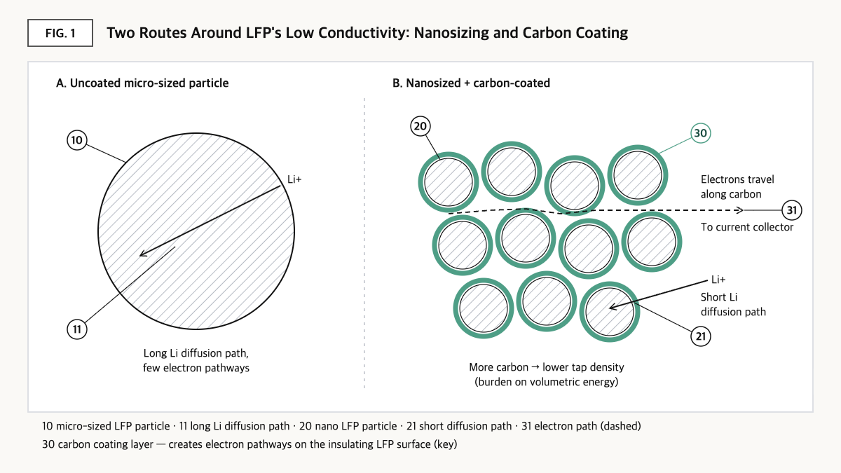
Source: reconstructed by the editorial team from Wang and Sun (2012) Energy & Environmental Science and Wu, Ren, and Li (2011) InTech.
The first solution is to split the village into smaller pieces, i.e., nanosizing. As particles become smaller, the distance lithium and electrons must travel shortens and the area in contact with the electrolyte widens[2]. The second solution is to pave roads around the village, i.e., carbon coating. When a carbon layer wraps the particle surface, electrons can travel along the conductive carbon layer rather than through the insulating LFP interior. It has been explained that carbon not only provides conductivity but also helps electrolyte penetration[2]. There are also reports that coating thickness can vary from about 1–2 nm to about 10 nm depending on raw-material conditions[1].
But paved roads also have a cost. Carbon’s density is about 40% lower than that of LFP, so adding too much lowers the tap density (the weight of powder that fills a given volume)[2]. In fact, there is a report that increasing carbon content from 3 wt% to 9 wt% lowers tap density from 2.15 g/cm³ to 1.66 g/cm³[1]. Splitting the village too finely is similar. For practical powders, a particle size range of 200–400 nm has been suggested[1]. In the end, both solutions share the feature of being a trade that gains performance per weight in exchange for part of the performance per volume.
③ Comparison — Three Routes to Raising Conductivity
| Route | How it works | Reported values | Cost |
|---|---|---|---|
| Baseline: uncoated LFP | — | Electronic conductivity 10-9–10-10 S/cm [1], theoretical capacity about 170 mAh/g [2] | Limited capacity utilization and power |
| Carbon coating | Forms electron pathways on the surface | Coating thickness about 1–2 nm to about 10 nm [1] | Tap density 2.15→1.66 g/cm³ as carbon goes 3→9 wt% [1] |
| Nanosizing | Shorter lithium/electron travel distance, larger reaction area [2] | Suggested range for practical powders 200–400 nm [1] | Fine-powder handling and volumetric density burden (qualitative) |
| Foreign-element doping | Changes conductivity of the crystal itself | Conductivity raised by about eight orders of magnitude, above 10-3 S/cm reported [2] | Burden of dopant selection and composition control (qualitative) |
Source: reconstructed by the editorial team from Wang and Sun (2012) Energy & Environmental Science[1] and Wu, Ren, and Li (2011) InTech[2].
What this table shows: Uncoated LFP’s conductivity stays in the 10-9 S/cm range[1], but carbon coating bypasses this by paving the surface, and in return tap density drops by about 23% as carbon content rises from 3 to 9 wt%[1]. Conductivity is something you buy, and you pay for it in volume.
④ Patent Perspective — Claiming Not Only “Nanoscale Size” but Also “the Volume Difference Between Two Phases”
As an example of capturing the result of nanosizing, consider US7939201B2 (title: Nanoscale ion storage materials including co-existing phases or solid solutions). The original assignee is A123 Systems Inc, and the Google Patents history shows the rights were subsequently transferred to Wanxiang Clean Energy USA Acquisition LLC (2013), then Lithium Werks Technology BV (2018), and in 2021 to RIL USA. Priority date 2005-08-08, filing date 2006-04-03, grant date 2011-05-10, legal status Active, adjusted expiration 2029-05-19[3].
What is interesting about this patent is that claim 1 does not directly limit particle diameter (nm) and instead claims an entire high power battery including the cathode material. In lithium transition metal phosphates such as LFP, a lithium-rich phase and a lithium-poor phase coexist during charge and discharge, and if the volume difference between the two phases is large, strain arises at the boundary. Claim 1 numerically limits the specific surface area (about 20 m²/g or more) together with the molar volume difference between these two phases. The specification explains that such behavior appears in nanoscale materials and also presents ranges such as a smallest cross-sectional dimension of about 75 nm or less and less than 3 wt% of a conductive phase that does not store lithium[3]. Restating claim 1 element by element gives the following.
| Element of claim 1 (restated) | Meaning for the scope of rights |
|---|---|
| (a) A high power storage battery including a cathode, an anode, an electrolyte, a cathode current collector, and an anode current collector | Battery (product) claim — where only cathode powder is supplied, indirect rather than direct infringement may become the issue |
| (b) The cathode electroactive material consists of a nanoscale lithium transition metal phosphate containing only one transition metal, with a specific surface area of at least about 20 m²/g | Single-transition-metal and surface-area limitation — LFP is the starting point, and compositions using two or more transition metals may fall outside the literal scope |
| (c) At least two co-existing olivine phases — a lithium-rich phosphate phase and a lithium-poor phosphate phase | Limits the structure at an intermediate state of charge/discharge — verifiable only by measuring at a specific state of charge |
| (d) The percentage molar volume difference between the two phases is less than about 6.4% | Limitation fixing the result of nanosizing as a physical property — the baseline for judging infringement |
| (e) Specific power of at least about 500 W/kg (1000 W/L) at specific energy of at least about 100 Wh/kg (205 Wh/L) | Battery performance limitation — cell-level test conditions may determine whether it is met |
Source: reconstructed by the editorial team from the granted claim structure of US7939201B2 on Google Patents and Justia Patents[3] (original claim language and drawings not reproduced verbatim).
This structure has an important implication for how to read the scope of rights. Had particle diameter been claimed, there would be room to escape by saying “our particles exceed 100 nm,” but claiming the specific surface area and the molar volume difference between two phases creates the possibility of falling within scope regardless of size if the resulting property is the same. Conversely, because the value can vary with measurement conditions (at which state of charge, and by which diffraction analysis the lattice volume is determined), this element is also a burden for the rights holder in proving infringement.
Design-around scenarios (including counterarguments). (a) Keeping particle size in the practical range (hundreds of nm) so that the specific surface area falls below about 20 m²/g or the molar volume difference between the two phases stays at about 6.4% or more could be a direction worth examining. (b) Adjusting doping and coating conditions so that phase behavior other than co-existing phases appears might also be raised. As counterarguments, since real powders have a particle size distribution, it may be argued that measuring only the fine-particle fraction satisfies the condition, and the interpretive breadth of the word “about” could also become a point of dispute. Weighing the remaining term until the adjusted expiration (2029-05-19) against the product launch timing is also a realistic option.
Cross-check of similar patents. MIT’s US7338734B2 (title: Conductive lithium storage electrode, priority date 2001-12-21, granted 2008-03-04), in which the same inventor (Yet-Ming Chiang) participated, claimed phosphate compositions with small substitutions of foreign elements to raise conductivity, and Google Patents lists it as Expired – Lifetime as of 2024-04-09[4]. Since the foundational rights on the doping route have lapsed while rights on the nanosizing route may still be alive, the FTO landscape differs by conductivity-improvement route even for the same LFP.
⑤ Limits and Outlook
On the optimistic side, carbon coating and nanosizing are already sufficiently mature technologies, and with the doping-family foundational patent also expired[4], barriers to entry in LFP cathode manufacturing may continue to fall.
There is also a contrary scenario. The more cell design goals shift from energy per weight to energy per volume, the more the “volume cost” paid by carbon and nanosizing could become a bottleneck again. The report that tap density drops noticeably as carbon content increases[1] suggests that existing optimum points may not hold in next-generation cells that require high-density electrodes.
The strategic alternative is to manage carbon content, particle size, and tap density as a single trade-off curve. Setting the conductivity target first and back-calculating the minimum carbon amount can reduce unnecessary volume loss. To add this article’s perspective: the patent risk of LFP conductivity-improvement technologies is more likely to be decided not by the process choice of “coated or nano” but by which claim’s numerical window the resulting physical properties (phase behavior, specific surface area, conductive-phase content) fall into.
Action to check (planning/IP teams): Obtain from your supplier the specific surface area (BET), particle size distribution, and carbon content analysis values for the LFP powder in use, and first compare whether they overlap with the specific surface area limitation in claim 1 of US7939201B2 (about 20 m²/g or more) and the ranges presented in its specification (smallest cross-section about 75 nm or less, conductive phase less than 3 wt%).
Items Requiring Verification
- In US7939201B2, the specific surface area (about 20 m²/g or more) is included in claim 1, but whether the cross-sectional dimension and conductive-phase content ranges are included in dependent claims was not verified at the level of original claim numbers.
- Whether the Korean, Chinese, and European counterparts of US7939201B2 remain in force was not separately verified in this article (the anticipated expiration of EP1938402B1, which appears to be a European counterpart, was shown as 2026-08-03, but its current status needs re-verification).
- Quantitative data on the degree of volumetric energy density reduction in nano LFP could not be confirmed in this work, so it is described only as a qualitative comparison.
Sources
- Jiajun Wang, Xueliang Sun, “Understanding and recent development of carbon coating on LiFePO4 cathode materials for lithium-ion batteries,” Energy & Environmental Science, 2012, DOI 10.1039/c1ee01263k. Link
- Borong Wu, Yonghuan Ren, Ning Li, “LiFePO4 Cathode Material,” Electric Vehicles – The Benefits and Barriers, InTech, 2011. Link
- Google Patents, US7939201B2 “Nanoscale ion storage materials including co-existing phases or solid solutions,” bibliographic data, claim 1, and assignment history (original checked 2026-09-23). Link · Granted claims: Justia
- Google Patents, US7338734B2 “Conductive lithium storage electrode,” bibliographic data and legal status (checked 2026-09-23). Link
This article is a technology and patent trend commentary, not legal advice. Specific FTO judgments require professional review.
Related Reading