Pressing an electrode by calendering to raise its density adds energy, but the pore paths ions must travel become narrower and more winding. This article sets out how porosity and tortuosity are intertwined, and reads the claim boundary through a granted patent from MIT and others that claims low-tortuosity pores running through the electrode.
① What’s the Topic
A calendering density specification looks like a number for “how hard it was pressed,” but in practice it is a tortuosity specification that decides how far ions must detour through the thickness.
Start with the industry context. After coating and drying, an electrode goes through calendering (roll pressing), passing between rolls to be compressed. This key step reduces the electrode’s pores to raise density and strengthen adhesion, and the stronger the compression, the more markedly porosity drops[3]. Because more active material fits in the same volume, this is welcome from an energy-density standpoint.
The tension lies in the fact that pores are the ions’ passageways. One review summarizes that higher porosity usually means lower tortuosity, which eases ion flow, but reduces electron conduction efficiency instead[3]. Pressing to tighten the electron path blocks the ion path, and loosening to open the ion path loses the electron path and energy density. On top of this, flat particles such as platelet graphite lie down sideways as they are pressed, adding the problem of tortuosity anisotropy, in which the path ions take through the thickness becomes especially long[4].
The question this article answers is this: How does calendering density change the ion path, and how far are designs that try to straighten that path tied up in patents?
② Basic Principle — Tortuosity Is “the Actual Steps on a Mountain Trail”
Even if the straight-line distance from the foot of a mountain to the summit is 1km, a zigzag trail may mean walking 3km. In an electrode, the straight-line distance is the electrode thickness, and the trail is the pores connecting the particles. Tortuosity (τ) is defined as the effective path length ions actually travel divided by the projected path length (the thickness)[1]. A straight tunnel gives 1, and the more winding, the larger the value.
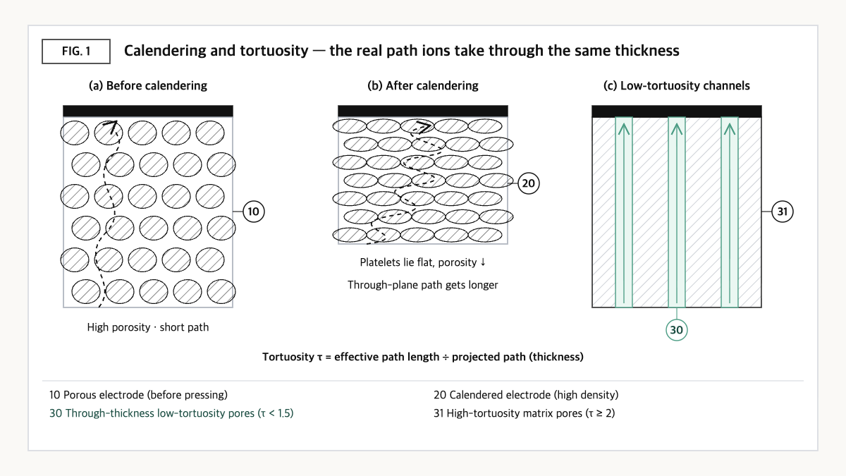
Source: reconstructed by the editorial team from the US9065093B2 specification and electrode microstructure studies.
The patent specification shows well why this number matters. Typical electrodes have a tortuosity of generally 3 or greater, and in conditions where ion transport governs performance, an electrode with tortuosity 3 must be one-third the thickness of an electrode with tortuosity 1 to deliver the same power[1]. In other words, tortuosity is a coefficient that directly eats into the “allowable electrode thickness.”
Calendering changes this trail in two ways. First, the pores themselves shrink, narrowing the path. Second, pressing rearranges the particles, making the path more winding. In particular, when platelet particles lie parallel to the electrode surface, the path may be relatively open in the in-plane direction, but ions must go around the particles in the through-plane direction. A study that analyzed electrode microstructure with X-ray tomography reported that such directional differences created by particle shape and compaction have a substantial impact on power and energy losses[4]. The Bruggeman relation, which estimates tortuosity from porosity alone, is widely used, but it is worth keeping in mind that with such anisotropy it can differ from the actual through-plane tortuosity.
③ Comparison — Conventional Calendered, Freeze-Cast, and Low-Tortuosity Channel Electrodes
| Axis | Conventional electrode (coated, calendered) | Freeze-cast (ice-templating) electrode | Low-tortuosity channel electrode (US9065093B2) |
|---|---|---|---|
| Tortuosity (τ, dimensionless) | Generally 3 or greater[1] | 1.7 (NCM712, 1.5 lower than a conventional electrode)[2] | Through channels below 1.5, matrix pores 2 or greater (claim 1)[1] |
| Porosity | Adjusted by calendering intensity, decreasing with stronger compression[3] | No sourced figure | Total 20–60%, of which channels account for 20–80% (claim 1)[1] |
| Thickness for the same power | Under ion-transport-limited conditions, a τ=3 electrode must be 1/3 the thickness of a τ=1 electrode for equal power[1] | ||
| Directionality | Anisotropy in which platelet alignment raises through-plane tortuosity[4] | Pores aligned in the ice-crystal growth direction (qualitative) | Pores running from one external surface of the electrode to another[1] |
| Reported performance example | — | — | At 2C discharge, specific capacity more than 3 times that of sintered electrodes of similar density (specification example)[1] |
Source: reconstructed by the editorial team from the US9065093B2 specification and claims[1], Sim et al. (2023)[2], Chen et al. (2025)[3], and a summary of Ebner et al. (2014)[4].
What this table shows: If a conventional electrode’s tortuosity is 3 or greater, the calculation shows that lowering it toward 1 alone could increase the allowable thickness for the same power by up to three times. Tortuosity is thus almost the only lever that loosens the power and thickness constraints at the same time without greatly sacrificing porosity.
④ Patent Perspective — Claiming the “Types and Shares” of Pores, Not Their “Amount”
The key patent is US9065093B2 (title: Controlled porosity in electrodes). On Google Patents its current assignees are listed as the Massachusetts Institute of Technology (MIT), the University of Michigan, Lawrence Berkeley National Laboratory and UC San Diego, and its inventors include Yet-Ming Chiang. Its priority date is 2011-04-07 (US provisional application), its filing date is 2012-04-09, it was published (US20120315538A1) on 2012-12-13 and granted on 2015-06-23; its legal status is Active (anticipated expiration 2033-08-14), with 20 granted claims[1].
| Elements of claim 1 (restated) | Meaning for the scope of rights |
|---|---|
| (a) An electrode including a matrix material having high-tortuosity pores with tortuosity of 2 or greater | Presupposes an ordinary porous electrode structure as the “base” |
| (b) Multiple low-tortuosity pores with tortuosity below 1.5 extend through the matrix from one external geometric surface of the electrode to another external geometric surface | Straight pores that “run through” are required — where the pores start and end may become an issue |
| (c) Total porosity of the electrode of 20–60% | Broadly covers the porosity range of practical electrodes |
| (d) Share of total porosity occupied by low-tortuosity pores of 20–80% | Key limitation — the range is set not by the total amount of pores but by the “share” between the two types of pores |
Source: reconstructed by the editorial team from the claim structure of US9065093B2 (original claim wording and drawings not reproduced verbatim).
This is a product claim that does not ask about the manufacturing method. Whether by freeze casting, laser processing or magnetic alignment, if the resulting electrode has all of (a)–(d), it may fall within the literal scope of rights. The dependent claims narrow the scope with a porosity of 29–39% and channel share of 25–47% (claim 2), a matrix comprising a ceramic (claim 11), and so on[1].
At the same time, this claim is structurally hard to prove. Tortuosity is defined as “effective path ÷ projected path”[1], but the actual value may differ depending on whether it is computed from X-ray tomography or measured electrochemically. In any dispute over the risk of infringement, how “below 1.5” and “2 or greater” are proven is likely to be the first gate.
Design-around scenario (with counterargument): The first axis to examine is the “run-through” element in (b). Grooves or pore patterns that penetrate only part of the thickness from the separator-side surface may not literally meet the element “from one external surface to another.” Designs that keep the electrode’s total porosity below 20% or above 60%, or limit the channel share below 20%, may also lie outside the literal scope. The counterargument goes like this. A channel that nearly penetrates the thickness after calendering could be argued to “substantially run through,” and a design tuning channel tortuosity just above 1.5 could be disputed within measurement scatter. However, this patent is expected to expire in 2033, so if mass production starts after expiry, the weight of the freedom-to-operate (FTO) judgment may change significantly.
Cross-check of similar patents: US10164242B2 in the same family (current assignees include the University of Michigan and MIT, anticipated expiration 2033-08-26) claims a method of forming a primary structure with aligned elongated regions and then removing part of a constituent to leave elongated pores, so product claims and method claims form a pair. SK On’s US12199265B2, dealing with dry-electrode compression ratio, is a patent that limits calendering conditions themselves, but its axis differs in that it claims a compression process window rather than pore geometry.
⑤ Limits and Outlook
On the optimistic side, tortuosity control is one of the few means that can ease the conflicting demands of thicker electrodes, fast charging and higher density at the same time. The specification example showing “more than 3 times the specific capacity at 2C”[1] and the tortuosity of 1.7 in a freeze-cast electrode[2] suggest that structural design alone can widen the performance range considerably.
The counter-scenario is process. Most methods for making low-tortuosity structures, such as freeze casting or sintering, sit uneasily with roll-to-roll coating and calendering lines. Moreover, active material is removed in proportion to the volume emptied for channels, so enlarging the channel share gives up part of the volumetric energy density. If speed and yield cannot be maintained on a mass-production line, tortuosity improvements may remain laboratory results.
The strategic alternative is to manage tortuosity first as a “quality indicator of the existing process” rather than as a “new process.” Recording through-plane tortuosity (or ionic resistance reflecting it) next to the calendering density specification makes it possible to find losses from platelet alignment without changing the process. This data can also serve as evidence, when channel structures are introduced later, of how far your design stands from the tortuosity and porosity windows in the claims.
Action to check (planning/IP teams): If you have projects on electrode pore structure such as laser patterning or magnetic alignment, check against US9065093B2 claim 1 whether the channels “run through” the electrode and whether total porosity and channel share fall within 20–60% and 20–80% respectively, and note the planned mass-production date alongside the 2033 expiry.
Items Requiring Verification
- The overseas family composition of US9065093B2 and its grant and maintenance status in each country were not checked this time.
- Specific figures on the porosity and directionality of freeze-cast electrodes were not found in the cited review, so they are described qualitatively.
- The original paper by Ebner et al. (2014) was not accessed; only the university news summary is cited.
- The specific form and exponent assumption of the Bruggeman relation used in the specification were not reviewed in detail.
Sources
- Google Patents, US9065093B2 “Controlled porosity in electrodes,” bibliographic data, specification and claims 1–20 (original checked 2026-09-23). Link / Bibliographic data of family member US10164242B2 (checked 2026-09-23). Link
- Yoon Bo Sim, Bo Keun Park, Ki Jae Kim, “Reasonable design of thick electrodes in lithium-ion batteries,” Frontiers in Batteries and Electrochemistry, 2023. Link
- Jiashen Chen et al., “Modelling of lithium-ion battery electrode calendering: A critical review,” Journal of Energy Storage, 2025. Link
- Purdue University School of Materials Engineering, “Tortuosity Anisotropy in Lithium-Ion Battery Electrodes” (summary of Ebner, Chung, García, Wood, Advanced Energy Materials, Vol. 4, No. 5, 2014). Link
This article is a technology and patent trend commentary, not legal advice. Specific FTO judgments require professional review.
Related Reading
- SK On’s Dry-Electrode Compression-Ratio Patent (US12199265B2) — The Narrow Window for Crack-Free Roll-to-Roll Calendering
- A Quieter Patent Than the 4680 — How Panasonic Used Graphite Particle Strength to Control Resistance Variation in Cylindrical Cells
- How Slurry Dispersion Pressure Affects Cell Performance — Why 3,500bar Ultra-High-Pressure Dispersion Technology Is Getting Attention