The N/P ratio is the first number in cell design: it sets how much more lithium the anode can accept than the cathode can deliver. It is usually described only as a safety margin against lithium plating, but taking apart one granted patent shows that this number also decides which state graphite settles into in the high-charge region.
① What’s the Topic
The N/P ratio is a safety-margin question of “how generously to size the anode,” and at the same time a design variable that chooses which structure graphite holds in the charge window where the cell is used most often.
Start with the industry context. One of the first values set when designing a lithium-ion cell is the N/P ratio (negative-to-positive capacity ratio): the anode capacity divided by the cathode capacity over the same facing unit area. During charging, lithium ions leave the cathode and enter the anode; if the anode runs out of room to host them, the excess lithium accumulates as metal on the anode surface. This is called lithium plating, and in severe cases it can grow into branch-like dendrites. The starting point of design is therefore that the N/P ratio must always be greater than 1[2].
The tension arises here. The more generously the anode is sized, the lower the plating risk, but the more “unused anode” the cell carries. Anodes that blend in silicon may need a larger margin than graphite[2], which tightens this tug-of-war further. On top of that, a patent granted in the United States in 2023 to a cell company claims that the N/P ratio is also linked to the “temporary output drop” after high-rate charging and discharging[1].
The question this article answers is this: How large a margin should the N/P ratio carry, and what else does that number change besides preventing plating?
② Basic Principle — The N/P Ratio Is the “Spare Spaces in a Parking Lot”
Think of charging as “cars arriving at a parking lot during the evening commute.” The cathode sends out the cars (lithium ions), and the anode is the parking lot that receives them. If the number of spaces exactly matches the number of cars, everything looks fine on paper, but if the spaces are drawn unevenly or some are blocked, cars end up parked illegally on the street. That illegal parking is lithium plating. So designers draw a few more spaces than there are cars.
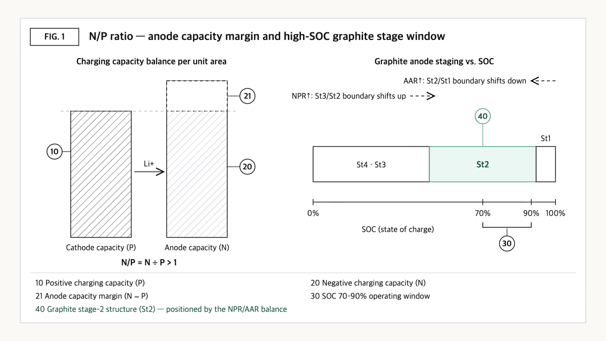
Source: reconstructed by the editorial team from the US11769904B2 specification and a cell design explainer.
That “few more” includes process tolerance. If coating thickness varies by 1% up or down, in the worst case the cathode is made 1% thicker and the anode 1% thinner. To keep the N/P ratio from dropping below 1 even then, the calculation shows the design value must be set to at least about 1.02[2]. The actual design margin is then set by adding anode degradation over life, lithium consumed on the first charge, and so on.
But the parking lot has floors. Depending on how much lithium enters, graphite passes in turn through stage-4, stage-3, stage-2 and stage-1 stage structures[1]. According to the patent specification, graphite’s volume change is large in the stage-1 structure and relatively small in the stage-2 structure[1]. The patent explains that if graphite sits in the stage-1 structure in the commonly used high-charge window (SOC 70–90%), repeated high-rate charging and discharging can make the electrode assembly swell and shrink rapidly over and over, pushing electrolyte out like a pump[1]. Changing the N/P ratio moves these stage boundaries along the SOC axis. The N/P ratio is both the number of parking spaces and the value that decides from which floor the cars start filling up.
③ Comparison — What Each N/P Design Zone Gains and Loses
| Design zone | N/P ratio (dimensionless) basis | Expected effect | Cost / caution |
|---|---|---|---|
| Insufficient margin | 1 or less | — | Anode lacks hosting space → risk of lithium plating and dendrites[2] |
| Minimum margin covering tolerance only | About 1.02 (assuming ±1% coating tolerance)[2] | Minimizes inactive anode | Does not cover degradation over life or first-cycle loss |
| Silicon-blended anode | May need a significantly higher value than graphite alone[2] | Uses high-capacity anode material | Margin offsets part of the energy-density gain (qualitative) |
| US11769904B2 claim 1 | NPR 1.45–1.90, AAR 0.75–0.90, NPR/AAR 1.60–2.55[1] | Aims to suppress output drop after high-SOC high-rate cycling[1] | Large anode margin raises the inactive-anode share (qualitative) |
| US11769904B2 claim 2 | NPR 1.05–1.40, AAR 0.55–0.65, NPR/AAR 1.60–2.55[1] | Same aim, lower-NPR zone | Paired with conditions of a large inactive-lithium share in the anode |
| Prior art (cited in the patent background) | Positive/negative capacity ratio 0.6–0.9 (about 1.11–1.67 as N/P when inverted)[1] | Vehicle cell design example | Inversion calculated by the editorial team |
Source: reconstructed by the editorial team from the US11769904B2 specification and claims[1] and a cell design explainer[2].
What this table shows: Accounting for tolerance alone lets the N/P ratio go down to about 1.02, yet the granted patent claims a much wider NPR range of 1.05–1.90 tied to an inactive-lithium index (AAR). This means that, even at the same N/P ratio, “good design” and “bad design” may diverge depending on how much inactive lithium is locked in the anode.
④ Patent Perspective — Claiming a “Ratio of Ratios,” Not a Single Number
The key patent is US11769904B2 (title: Nonaqueous electrolyte secondary battery) held by Prime Planet Energy & Solutions. Its priority date is 2020-08-11 (Japanese application 2020-135765), its US filing date is 2021-07-12, it was published (US20220052373A1) on 2022-02-17 and granted on 2023-09-26, and its legal status on Google Patents is Active (anticipated expiration 2041-10-26). It has 2 granted claims, both independent[1].
Two terms need clarifying first. NPR is the anode charging capacity divided by the cathode charging capacity, effectively the N/P ratio. AAR is the anode’s effective discharging capacity divided by the sum of that effective discharging capacity and the capacity corresponding to “inactive lithium” locked in the anode and no longer usable[1]. The specification explains that a larger NPR shifts the stage-3/stage-2 boundary toward higher SOC, and a larger AAR shifts the stage-2/stage-1 boundary toward lower SOC, and argues that their ratio (NPR/AAR) places graphite’s stage-2 structure in the SOC 70–90% window[1].
| Elements of claim 1 (restated) | Meaning for the scope of rights |
|---|---|
| (a) A nonaqueous electrolyte secondary battery having an electrode assembly and an electrolyte solution, with at least part of the assembly impregnated with the solution | Covers most ordinary lithium-ion cells — little limiting effect |
| (b) The assembly includes a positive electrode, a negative electrode and a separator, the separator separating the two electrodes | Ordinary configuration |
| (c) The negative electrode active material includes graphite | Limited to graphite systems — may be met if any graphite is used |
| (d) NPR/AAR is at least 1.60 and at most 2.55 | Key limitation — the range is set not by the N/P ratio alone but by its ratio to an inactive-lithium index |
| (e) Additionally satisfies NPR 1.45–1.90 and AAR 0.75–0.90 at the same time | Narrows claim 1’s window to the high-NPR zone (claim 2 covers NPR 1.05–1.40, AAR 0.55–0.65) |
Source: reconstructed by the editorial team from the claim structure of US11769904B2 (original claim wording and drawings not reproduced verbatim).
The center of gravity of the scope of rights is (d) and (e). What is interesting is that AAR is not a “number on the design drawing” but a state quantity measured after manufacturing and activation. Even cells built from the same drawing may show different AAR values depending on formation conditions or measurement timing, so in any dispute over the risk of infringement, “which cell was measured, when, and by what method” is likely to become the first issue. The specification describes a measurement approach using a single-electrode cell and dV/dQ analysis[1], and this approach may serve as the baseline for claim construction.
Design-around scenario (with counterargument): On a literal reading, designs that fall between the windows of the two claims come to mind first, such as NPR between 1.40 and 1.45, or AAR between 0.65 and 0.75. For example, a cell with NPR 1.20 and AAR 0.80 has NPR/AAR of 1.50 and falls outside (d) from the start. The counterargument is clear, however. Because AAR changes as cycling progresses, it could be argued that a cell outside the range at shipment enters the range during use. And while numerically limited inventions are generally understood to have limited room for the doctrine of equivalents, it is hard to rule out that near-boundary designs within measurement scatter could become the subject of a dispute. So if a design-around is chosen, keeping NPR and AAR measurement records both at shipment and at end of life is likely to strengthen the defense.
Cross-check of similar patents: The background of this patent cites Japanese Laid-Open Patent No. 2002-203608, which sets a positive/negative capacity ratio of 0.6–0.9, as prior art[1]. Ranges for the N/P ratio alone have long been in the public domain, and US11769904B2 reads as an attempt to differentiate by adding new axes: “inactive lithium” and “graphite stage structure.”
⑤ Limits and Outlook
On the optimistic side, the view that recasts the N/P ratio from a “safety factor against plating” into an “operating-window optimization variable” could widen design room for vehicle cells that see frequent fast charging and repeated high power. With the same materials, adjusting only the N/P ratio and activation conditions may change behavior in a specific SOC window[1].
There is also a counter-scenario. The specification itself states that the mechanism it presents (electrolyte pumping driven by graphite volume change) “includes a presumption”[1]. In anodes with a growing silicon share, the main source of volume change becomes silicon rather than graphite, so the logic of tuning the window through graphite stage structures may not carry over as-is. In that case, the weight of the N/P margin shifts back to its original role of preventing plating.
The strategic alternative is to manage the N/P ratio not as a single design value but as values at three points in time: design N/P, effective N/P after activation, and end-of-life N/P. Technically this lets plating margin and operating window be checked together; on the IP side it provides evidence, point by point, of the distance from claims that use an inactive-lithium index.
Action to check (planning/IP teams): Put your graphite-based cells’ NPR and post-activation inactive-lithium ratio (the value corresponding to AAR) into a single table, and first check whether the two values overlap the windows of US11769904B2 claims 1 and 2 (NPR/AAR 1.60–2.55). If they do, it is advisable to request a separate freedom-to-operate (FTO) review that includes the measurement method and timing.
Items Requiring Verification
- The family composition of US11769904B2 in Japan, China and elsewhere, and its grant status in each country, were not checked this time.
- The statement that “silicon-blended anodes may need a higher N/P ratio” rests on a single explainer source, and no specific recommended value was confirmed.
- No quantitative data on how much N/P margin reduces cell energy density (Wh/kg) was obtained this time, so it is described only qualitatively.
- Prior art JP2002-203608 was confirmed only as cited in the US11769904B2 specification; the original was not separately reviewed.
Sources
- Google Patents, US11769904B2 “Nonaqueous electrolyte secondary battery,” bibliographic data, specification and claims 1–2 (original checked 2026-09-23). Link
- Kerem Batuş, “Why N/P Ratio Matters in Lithium-Ion Cells,” Battery Design, 2025-09-05 (modified 2025-12-09). Link
This article is a technology and patent trend commentary, not legal advice. Specific FTO judgments require professional review.
Related Reading