Making a cell longer and wider reduces the number of parts, but it also makes it harder for current and heat to spread evenly inside the cell. This article explains what changes as you move away from the tab, and how patents are fencing in this problem.
① What’s the Topic
In a large-area cell, the real problem is not the average temperature but the temperature spread within a single cell. The longer the distance current must travel to reach the tab, the more some parts of the electrode overwork while others sit idle.
Start with the industry context. In both EV packs and energy storage systems (ESS), there is a clear trend toward making cells larger to reduce their number. Fewer cells mean fewer weld points, busbars, and sensor wires. A patent claiming a pack filled with long-format cells longer than 600 mm has already been granted[4].
The source of tension lies inside the cell. An electrode is a thin metal foil, the current collector, coated with active material. Electrons must travel from the site of reaction along the current collector to the tab. As the cell grows, this travel distance increases, and the electrical resistance of the current collector creates a potential difference between areas near and far from the tab. This difference turns into non-uniform current density, and then into non-uniform heat generation and degradation.
So the question this article answers is: what happens inside a cell as you move away from the tab, and how do design and patents deal with that non-uniformity?
② Basic Principle — Why the House at the End of the Water Main Has Weak Pressure
Picture the water mains of an apartment complex. Homes near the main line (the tab) get strong pressure, while those at the end of the pipe get weak pressure, because friction losses grow as the pipe gets thinner and longer. The current collector of an electrode is exactly this thin, long pipe. Because aluminum and copper foils are very thin, the resistive loss, the equivalent of “pipe friction,” can no longer be ignored as the area grows.
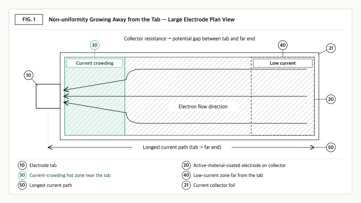
Source: reconstructed by the editorial team from the large-cell electrochemical-thermal analyses of Zhao et al. (2014) and Lee et al. (2021).
This loss shows up in two forms. First, areas near the tab have less potential loss, so reactions occur there earlier and more intensely. During charging these areas fill first; during discharging they empty first. Second, where current concentrates, Joule heat and reaction heat both increase, creating local hot spots. Because higher temperature lowers reaction resistance and draws even more current, the non-uniformity reinforces itself.
Research using three-dimensional electrochemical-thermal models has quantified this phenomenon. One analysis showed that adjusting tab positions in large cells to reduce electron transport losses in long electrodes significantly increases usable energy density, and that there is a quantitative relationship between current density variation and usable energy density[1]. Another study on 45 Ah lithium iron phosphate (LFP)/graphite pouch cells reported that the cell aspect ratio has the greatest effect on temperature distribution, because it changes the longest current pathway and the distance between tabs. It also found that the position of the positive tab, on the higher-resistance aluminum current collector side, governs the maximum temperature and the temperature difference[2].
Here is this article’s perspective in one line. Part of a large cell’s “usable capacity” is determined not by materials but by the length of the current path. Even with the same materials, the energy you can actually extract, and the service life, change with tab layout.
③ Comparison — Current Path and Temperature Spread by Tab Layout
| Tab layout | Longest current path | Internal temperature spread tendency | Basis / values |
|---|---|---|---|
| Nominal tab (positive and negative tabs side by side on one edge) | Long (to the far end opposite the tabs) | Hot near tabs, cool at the far end | 45 Ah LFP pouch, ΔT 1.18°C after optimization[3] |
| Counter tab (positive and negative tabs on opposite edges) | Relatively short and symmetric | Tends to give the most even distribution | ΔT 1.12°C after optimization, 77.2% reduction from the initial design[3] |
| L-shaped tab | Intermediate | Possible bias toward corners | ΔT 1.31°C after optimization[3] |
| Long cell with terminals at both lengthwise ends (current direction = cell length direction) | Grows in proportion to cell length | Large heat-dissipation area, but lengthwise gradients must be managed | Qualitative comparison (patent specification description)[4] |
Source: reconstructed by the editorial team from the 45 Ah LFP/graphite pouch cell simulation results of Lee et al. (2021, Applied Thermal Engineering) and the specification of US12113227B2. ΔT values are optimized design values from the same study; the long-cell both-end row is a qualitative comparison.
What this table shows: Even for the same 45 Ah cell, changing the tab type and optimizing the aspect ratio and tab positions reduces the internal temperature difference by the mid-to-high 70% range compared with the initial design[3]. Tab layout is not a component choice but a first-order design variable that determines a cell’s thermal performance.
④ Patent Perspective — A Claim That Fixes Cell Dimensions and Pack Space Utilization, Leaving the Current-Path Solution Open
The patent to watch in large-area cell design is US12113227B2 (title: Cell, power battery pack, and electric vehicle), held by BYD. The original applicant and current assignee is BYD Co Ltd; the priority date is 2019-01-09 (six Chinese applications), the filing date 2019-06-21 (international application PCT/CN2019/092349; US application number 17/422,084), and the grant date 2024-10-08. Its legal status is shown as Active (anticipated expiration 2040-01-21)[4][5]. The specification describes an embodiment in which the first electrode tab is placed at one lengthwise end of the cell body and the second electrode tab at the other end, so that the current direction matches the cell length direction.
| Elements of claim 1 (paraphrased) | Meaning for the scope of rights |
|---|---|
| (a) A power battery pack including a housing and a plurality of cells provided in the housing | Subject limitation — claimed at the pack level, not the cell alone |
| (b) Each cell body has a length L, a width H, and a thickness D, with L greater than H and H greater than D | Shape limitation — a flat, long rectangular body |
| (c) L exceeds 600 mm | Absolute dimension limitation |
| (d) The cell body volume V is 953,750 mm³ or more | Lower size bound — excludes small long cells |
| (e) L/H is in the range of 4 to 21 | Aspect-ratio numerical limitation |
| (f) The cell is a prismatic cell with an aluminum casing | Enclosure limitation — pouch, cylindrical, and other metal casings literally excluded |
| (g) The ratio of the total cell volume V1 to the pack volume V2 (V1/V2) is 55% or more | Pack space-utilization limitation — the key limitation tying cell shape to pack-structure performance |
Source: reconstructed by the editorial team from the Google Patents bibliographic data and the granted US claim 1 published on Justia Patents (original claim wording and drawings not reproduced).
Two points stand out. First, granted claim 1 is directed not to a cell but to a power battery pack, bundling cell dimensions (L > 600 mm, L/H 4 to 21, volume of 953,750 mm³ or more), an enclosure condition of a prismatic cell with an aluminum casing, and a space-utilization condition of total cell volume at 55% or more of pack volume[5]. Second, claim 1 contains no limitation on tab position or current path. The both-end terminal structure, with tabs at both ends of the cell in the length direction, is limited only in a dependent claim (claim 15)[5]. In other words, this patent first secures “what shape of cell, packed how tightly into the pack,” not “how the non-uniformity is solved.”
Design-around scenario (with counterargument): Because claim 1 has many limitations, there are several paths that literally fall outside it. Designs with (a) a cell length of 600 mm or less or an L/H outside 4 to 21, (b) a cell volume below 953,750 mm³, (c) a non-aluminum casing or pouch cell, or (d) a pack space utilization (V1/V2) below 55% may fall outside the scope of claim 1. The counterarguments are equally clear.
Options (a) and (d) reduce the very advantages of long cells and module-free pack structures, and option (c) brings cost and stiffness burdens from changing the enclosure material. Also, the fact that claim 1 is a pack claim does not free cell suppliers from risk. If a customer’s pack satisfies all limitations, supplying the cells could become an indirect infringement issue. Of the 17 granted claims in the US gazette, the only independent claim is claim 1, directed to the pack[5].
An “improvement” to the current path, such as adding multiple tabs inside the cell, may be patentable in its own right but does not remove the risk of infringement of claim 1. A freedom to operate (FTO) assessment should consider all claims and the same family together (such as US20220102787A1, shown as a related application on Google Patents).
Similar-patent cross-check: In cylindrical cells, the approach of removing the tab and collecting current along the entire electrode edge, for example Tesla’s tabless patent (US11749842B2), solves the same problem of “shortening the current path” with a completely different structure. In portfolio analysis, it is worth distinguishing that shape claims and current-collection structure claims sit at different layers.
⑤ Limits and Outlook
Optimistically, long cells with terminals at both lengthwise ends could establish themselves as a way to offset the drawbacks of cell enlargement through structure, by reducing pack part counts and widening the heat-dissipation area per cell[4].
There is also a counter-scenario. Under high-current conditions such as fast charging, the disadvantage of a long current path is amplified. If temperature and current-density gradients form along the cell length, certain sections may degrade first, and this spread is hard to detect in cell-level average tests. The larger the cell, the more likely a state of “normal on average, abnormal locally” may stay hidden for a long time.
The strategic alternative is to shift the cell evaluation metric from average temperature to internal temperature difference (ΔT). Since, as the research shows, aspect ratio and tab position alone can change ΔT substantially[2][3], specifying ΔT measurement conditions (current, measurement-point locations, cooling conditions) in cell purchase specifications and supplier comparison sheets makes comparisons between large cells much fairer.
Action to check (planning/IP teams): Compare the long cell and pack design under review one-to-one with the seven limitations of claim 1 of US12113227B2 (L > 600 mm, L/H 4 to 21, cell volume of 953,750 mm³ or more, aluminum-cased prismatic cell, pack space utilization of 55% or more, etc.); if all are met, include an FTO review extended to all claims and the family in the cell selection schedule.
Items Requiring Verification
- Whether the long cells and packs BYD actually mass-produces fall within the numerical ranges of claim 1 of US12113227B2 has not been confirmed against official specifications.
- The detailed figures in each of dependent claims 2–17 of US12113227B2 were not individually reviewed in this article, except claim 15 (tabs at both ends).
- The Chinese, European, and Korean counterpart family members of US12113227B2 and the scope of their granted claims were not checked in this article.
- The claims of the related application US20220102787A1 were not reviewed separately.
- The ΔT values in the text are simulation results for a 45 Ah LFP pouch cell; no basis was confirmed that they apply directly to large prismatic cells.
Sources
- W. Zhao, G. Luo, C.-Y. Wang, “Effect of tab design on large-format Li-ion cell performance,” Journal of Power Sources 257 (2014) 70–79. Link
- J.-J. Lee et al., “The Effect of Tab Attachment Positions and Cell Aspect Ratio on Temperature Difference in Large-Format LIBs Using Design of Experiments,” Energies 14(1) 116 (2021). Link
- J.-J. Lee et al., “Design optimization of tab attachment positions and cell aspect ratio to minimize temperature difference in 45-Ah LFP large-format lithium-ion pouch cells,” Applied Thermal Engineering 182 (2021) 116143. Link
- Google Patents, US12113227B2 “Cell, power battery pack, and electric vehicle,” bibliographic data (original checked 2026-09-23). Link
- Justia Patents, US 12,113,227 granted claim 1 and application data (checked 2026-09-23). Link
This article is a technology and patent trend commentary, not legal advice. Specific FTO judgments require professional review.
Related Reading