1. What’s at Stake
Electrolyte injection is one of the “oldest” process steps in cell manufacturing, yet from a claim-scope standpoint there is still unsettled territory. The key is not whether vacuum is used, but when the pressure reduction begins and how many times it repeats.
Let’s start with the industry context. In laminate (pouch) cells, injection is fundamentally an impregnation problem — getting electrolyte to “soak into” the electrode stack. Insufficient impregnation raises local resistance and shortens cycle life. For a long time, the standard approach has been to use reduced pressure (vacuum) to draw air out of the pores and push electrolyte in. This is where the tension arises — if the reduced-pressure approach has been known for more than 20 years, what did a later-filed injection patent actually secure as its claim?
This piece finds the answer by examining the claim structure of US10476097B2 (titled “Method of manufacturing secondary battery and apparatus for the same”).
2. The Basic Mechanism — Two Ways to Soak a Sponge in Water
Think of the electrode stack as a dry sponge and the electrolyte as water. Dip the sponge in water, and the outside wets quickly, but the inside stays dry because air gets trapped.
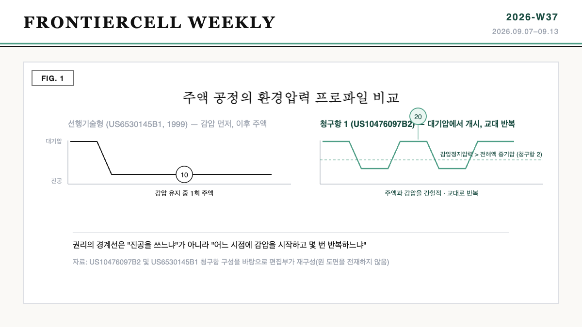
Source: editorial reconstruction based on the claim structures of US10476097B2 and US6530145B1 (not a reproduction of the original drawings).
One method is to put the sponge in a vacuum chamber, draw out the air first, and then pour in the water. It’s intuitive, and in fact an old approach. The other method is to pour in a little water first, then repeatedly raise and lower the pressure, like squeezing and releasing the sponge. As pressure drops, the trapped air escapes; as it rises again, water is pushed into the space the air left behind. Repeating this back-and-forth several times wets the interior without ever pulling a single deep vacuum.
US10476097B2 claims the second approach. But one more important condition is attached — injection begins under atmospheric-pressure conditions, not vacuum. Only after that do injection and pressure reduction alternate.
3. Comparison — Bibliographic Data of the Two Patents
| Item | US10476097B2 | US6530145B1 (Prior Reference) |
|---|---|---|
| Title | Method of manufacturing secondary battery and apparatus for the same | Fixture and method for liquid electrolyte impregnation of a battery cell |
| Current assignee | Envision AESC Energy Devices Ltd | Alcatel Lucent SAS (original applicant Alcatel SA) |
| Priority / filing date | 2015-04-16 (JP2015-084219) / 2016-03-29 | 1999-09-28 / 1999-09-28 |
| Grant date | 2019-11-12 | 2003-03-11 |
| Number of claims | 4 | 10 |
| Legal status | Active, expected expiration 2036-06-19 | Expired – Fee Related |
| Core of pressure operation | Injection begins at atmospheric pressure → injection and pressure reduction performed intermittently and alternately | Vacuum formed inside a fixture (nest) → electrolyte then injected through a fill port |
What this table shows: the 1999 filing had already secured the basic skeleton of “vacuum, then injection” (now expired), and US10476097B2, filed 16 years later for the same purpose, staked its claim on a different axis — the temporal sequence of pressure changes. In other words, what the later filing secured was not a new physical phenomenon, but an operating sequence.
4. Patent Perspective — Claim Mapping and Design-Around Points
Breaking down the elements of claim 1 gives the following. Mapping them 1:1 against the prior reference reveals exactly where the claim boundary is drawn.
| Element of Claim 1 (US10476097B2) | Corresponding Feature in US6530145B1 | Assessment |
|---|---|---|
| (a) Inserting an electrode stack, in which cathode and anode are stacked with a separator between them, into an outer case | Housing the electrode assembly in the fixture’s nest | Substantially identical — low contribution to novelty |
| (b) Sealing the outer periphery except for a portion, and using the unsealed portion as a fill port | Using the cap’s fill port as the injection port | Functionally similar |
| (c) Beginning injection under atmospheric-pressure conditions | No corresponding feature (vacuum formed before injection) | Core distinguishing feature |
| (d) Performing injection and ambient-pressure reduction intermittently and alternately | No corresponding feature (single sequence) | Core distinguishing feature |
| (e) Intermittently injecting the same electrolyte | No corresponding feature | Limiting feature |
| [Claim 2] Pressure-reduction stopping point > vapor pressure of the electrolyte | – | Dependent-claim limitation — a second gate for the design-around analysis |
Source: editorial element-by-element comparison based on the published claim language of both patents; this is not a legal opinion on infringement.
Design-around points. Elements (c) and (d) are required elements joined by “and,” so there is substantial room to argue that literal infringement of claim 1 does not arise if either one is missing. The design-around directions worth examining in practice are as follows.
- Change the starting point: Begin injection in a chamber that is already under reduced pressure, rather than at atmospheric pressure — possibly failing to meet element (c).
- Dismantle the alternating structure: Lower the pressure once in a single monotonic profile and inject continuously — possibly failing to meet the “alternately” requirement of element (d).
- Switch the pressure direction: Drive impregnation with inert-gas pressurization instead of pressure reduction — though this direction risks conflicting with a different family of prior and later patents, requiring a separate FTO review.
Rebuttal to the design-around scenario. Even if the above design-arounds hold up literally, they carry two risks. First, the doctrine of equivalents. Even if a recipe that repeats “reduce pressure, then return to atmospheric” two or three times is called by a different name, such as a “periodic pressure swing,” a finding of equivalent infringement may be hard to avoid if the function and effect are substantially the same. Second, there is a cost in process performance. If the claimed profile is in fact effective at shortening impregnation time, the design-around recipe will lose out on takt time or impregnation variance. This is why a design-around should not be a legal judgment alone, but a joint decision made together with process engineers.
One more point worth noting is the patent family. This case was filed via PCT/JP2016/060143 (WO2016167116A1), so corresponding family members may exist in countries other than the U.S. For a recipe to be applied to a Korean or Chinese production line, the registration status and claim language in each relevant jurisdiction must be checked individually — a judgment should not be made from the U.S. claims alone.
5. Limits and Outlook
First, let’s be clear about the limits. This piece is only an element-by-element comparison based on published claim language, not a legal opinion on infringement. An actual determination would need to also examine the specification’s term definitions, the prosecution history, and the claim-construction case law of the relevant jurisdiction. In addition, this article does not assert that US6530145B1 is a cited reference of this patent; it was used only as a reference prior-art comparison within the same technical field.
Counter-scenario to the optimistic outlook. There is also a scenario running counter to the common belief that “process-parameter patents are easy to design around.” The injection pressure profile is recorded directly in the equipment’s PLC recipe, and it is common for an equipment vendor to transplant similar recipes across multiple customers. In other words, the evidence needed to prove infringement remains inside the equipment. This could actually be a type of patent that is easier to prove than a chemical-composition patent.
Strategic alternative. Rather than working out a design-around first, filing a defensive patent on your own recipe’s pressure profile ahead of time may offer a better cost-benefit outcome. Because sequence-type claims leave wide room for variation, being first to file is itself a negotiating card.
Action item (for planning/IP staff): Check whether the ‘pressure-reduction start point’ and the ‘number of pressure-reduction/injection repetitions’ among your own injection equipment’s recipe parameters are specified numerically in your design documents. Without these two values documented, neither an FTO review nor a defensive filing can begin.
Also in This Week’s Frontiercell Weekly
FRONTIERCELL WEEKLY 2026-W37 · 2026.09.07–09.13
- The Year Equipment Shows Got an ‘EV Fire Special Zone’ — What K-Battery Show 2026 Revealed About the Center of Gravity in Equipment Orders
- Every Time a Satellite Enters Shadow — Where Space-Grade Batteries Diverge from Ground Cells
- [Patent Analysis] The Sun That Warms Also Locks the Heat Path — The Claim Boundary of Lockheed Martin’s Satellite Battery Thermal Management Patent (US7967256B2)
Pingback: The Year Equipment Shows Got an ‘EV Fire Special Zone’ — What K-Battery Show 2026 Revealed About the Center of Gravity in Equipment Orders - Frontiercell