To state the conclusion first: the bottleneck in dry electrodes is not removing the solvent — it is finding a binder to take over the job the solvent used to do.
Secondary battery electrodes have, until now, been made by dissolving active material, conductive additive, and binder in a solvent (NMP) into a slurry, coating it onto the current collector, and passing it through a long drying oven to drive off the solvent. This drying section takes up a significant share of the electrode process line’s length and a large portion of the process energy. On top of that, NMP requires its own recovery and purification equipment. The dry electrode is the idea of eliminating this section altogether.
This is where the tension arises. The solvent was never a mere medium — it has also handled dispersing particles evenly and coating the binder uniformly onto the active-material surface. Take the solvent away, and those two functions have to be secured by other means. The question this article sets out to answer is a single one: why does the binder become the factor that narrows the freedom of material choice in dry electrodes, and how does that constraint show up in the patent landscape?
Basic Principle — Spinning “Cotton Candy” Instead of Kneading Dough
If the wet process is like kneading dough, the dry process is closer to spinning cotton candy. The wet process mixes powder with water, spreads it out, and dries it; the dry process instead applies friction and shear force among the powder particles to stretch the binder out into threads, letting those threads catch the active-material particles like a net.
This “thread-spinning” is called fibrillation, and the material best known for this property to date is PTFE (polytetrafluoroethylene). Under shear, its particles elongate to form a fibrous network on the order of a few micrometers, making it possible to produce a self-supporting film without any separate solvent.
The problem is that PTFE is unstable in a reducing atmosphere. In a low-potential environment like the anode, PTFE has been reported to react with lithium and decompose, which is why the dry process has established itself on the cathode first, with anode application following behind. On top of that, the binder content itself is a dilemma. Making the fiber network denser requires more binder, but the binder is electrochemically idle weight and resistance, so it eats into energy density and power output at the same time.
Comparison — What Wet and Dry Trade Off
| Item | Wet (Slurry Coating) | Dry (Solvent-Free Film) |
|---|---|---|
| Solvent | Uses NMP etc., requires recovery/purification equipment | Not used, no recovery equipment needed |
| Drying process | Long drying oven required (heavy equipment length and energy burden) | Drying oven can be eliminated |
| Binder selection range | Wide, various options like PVDF chosen by solvent solubility | Effectively limited to fibrillatable materials (mainly PTFE) |
| Thick electrodes | Binder segregation worsens as thickness increases during drying | Fewer segregation factors, relatively favorable for thick electrodes |
| Anode application | Few constraints | High difficulty due to binder reduction-stability issues |
| Mass-production maturity | Decades of accumulated experience, stable yield | Pilot-to-early mass production stage, uniformity is the key issue |
Source: qualitative comparison compiled by the editorial team from the article analysis and the US11777070B2 and US20150303481A1 publications
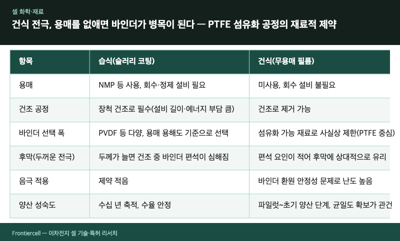
What this table tells us — what the dry electrode sells is “process cost,” and what it pays instead is “freedom of material choice.” That is why dry processing becomes more economical the thicker the electrode is (i.e., the more a thick electrode is chosen for energy density), while its advantage shrinks for thin, high-power electrodes.
Source: reconstructed by the editorial team from the article text and the claims of US11777070B2
Patent Perspective — The Scope of Rights Splits into “Composition” and “Apparatus”
The dry electrode patent landscape has broadly two axes: one is film composition, and the other is the apparatus and process that makes the film.
A representative example on the composition axis is U.S. granted patent US11777070B2 (“Compositions and methods for dry electrode films having reduced binder content,” originally assigned to Maxwell Technologies and now held by Tesla, granted 2023). Judged by its core effect, the focus of the right is on obtaining a self-supporting dry electrode film while lowering binder content — a way of solving, through composition design, the “binder is both resistance and weight” dilemma discussed above. An earlier publication in the same family, US20150303481A1 (“Dry energy storage device electrode and methods of making the same”), is also cited alongside it, and serves as the starting point when reading the prior-art flow of dry-electrode-family filings.
What matters in practice is the axis along which an FTO (infringement) judgment is made. Composition claims are generally defined by ingredient and content ranges, so infringement exposure narrows down to “does our electrode’s binder type and content fall within that numerical range?” Apparatus/process claims, by contrast, are defined by a combination of components such as the shear-application method, roll-press conditions, and film transport structure, so missing even a single component can open the possibility of escaping literal infringement.
Design-around approach (rebuttal scenario) — that said, a design-around is hard to call easy. First, a design that departs from the content range usually comes with a performance penalty, so it tends to end up “avoided but unusable.” Second, switching the fibrillating binder to a material other than PTFE is possible in principle, but the substitute material itself may fall within another applicant’s scope of rights. Third, once the doctrine of equivalents is factored in, a numerical limitation alone is hard to guarantee as safe. The realistic path is less a design-around on its own and closer to building up one’s own filings on the process axis to create cross-license negotiating leverage.
Limitations and Outlook
The optimistic outlook is clear — eliminate the drying oven and factory floor space and process energy both shrink, and for families such as solid-state batteries, where a liquid slurry is hard to use in the first place, dry processing becomes effectively a required path.
An opposing scenario needs to be weighed too. The real bottleneck of dry electrodes is not the principle but large-area uniformity. Wet processing has decades of accumulated know-how for managing coating-thickness variation, whereas in a dry film, local binder-distribution variation carries straight through into resistance variation and lifespan variation. If uniformity yield fails to reach existing wet-line levels, the drying cost saved could be offset by the defect rate, erasing the total-cost advantage. In that case, dry processing could end up confined to the narrow niche of a solid-state/thick-electrode-specific process rather than becoming “the standard for every electrode.”
Strategic alternative — instead of the binary choice of converting the entire line to dry, a hybrid configuration can be considered — dry for the cathode only, wet for the anode. Leaving the anode, where the binder reduction-stability problem is concentrated, on wet processing lowers material risk while still shedding a substantial share of the drying-oven burden.
What planning and IP staff should check now — first identify the binder type and weight percent in the dry electrode design under review, and check, family by family via KIPRIS and Google Patents, whether that figure overlaps with the content range of the Maxwell/Tesla-family composition patents. If overlap is confirmed on the composition axis, building up your own filings on the process axis first is more likely to be the advantageous negotiating card than a design-around.
This article is a technical explainer based on publicly available patent documents and industry-disclosed material, and is not legal advice on whether any specific product infringes. Registration and litigation outcomes cannot be predicted with certainty.