A bipolar electrode is a structure in which a cathode is applied to the front of a single current collector and an anode to the back, and many such sheets are stacked. This article explains, together with a patent, what improves when series connection, once made between cells with bus bars, is moved inside the cell, and where things become harder in return.
① What’s the Topic
Both the technical challenges and the patent fences of the bipolar structure are concentrated not in the middle of the electrode but at its edges. If the seal between layers leaks even slightly, the series structure built up inside the cell itself collapses.
Start with the industry context. In July 2021, Toyota fitted a bipolar nickel-metal hydride battery to the all-new Aqua and stated that its output was approximately two times higher than the previous generation[1]. Toyota Industries, which has long developed batteries for electric forklift trucks, is said to have contributed analysis technologies to its development[1]. Then, in June 2023, Toyota announced that it would extend the bipolar structure used in hybrid vehicles to battery electric vehicles (BEVs), and that it was developing a popularization-version bipolar battery based on lithium iron phosphate (LFP) with a 2026–2027 target[3].
The tension hides behind the simplicity of the structure. Parts decrease and resistance falls[2], but because multiple voltage units are stacked inside one cell, the units must be perfectly isolated from one another. As long as a liquid electrolyte is used, this isolation depends on edge sealing.
So the question this article answers is this: By what principle does a bipolar electrode stack voltage inside the cell, and which part of that structure did patents claim as a right?
② Basic Principle — Instead of Many Detached Houses, an Apartment Where Each Floor Is the Ceiling Below
The common cell structure is called monopolar. The same polarity is applied to both sides of one current collector (the metal foil that gathers current), for example cathode on both sides, and inside the cell, like polarities are gathered in parallel. To raise voltage, many such cells are connected in series outside the cell with bus bars. It is like connecting many detached houses with alleys (bus bars).
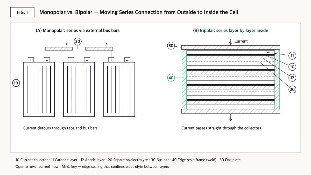
Source: reconstructed by the editorial team from Toyota announcement (2021), Toyota Industries material, and the claims of US11735743B2.
Bipolar is different. A cathode is applied to one side of a single current collector and an anode to the other side[1][2]. When many of these ‘bipolar electrodes’ are stacked with separators and electrolyte in between, the anode of one electrode faces the cathode of the next, forming one voltage unit. Because the current collector is both the end of one unit and the start of the next, current passes straight through the collector in the thickness direction. It is like an apartment in which the floor of one level is the ceiling of the level below. With the alleys gone, parts decrease, and because current flows a short distance across a wide area, internal resistance also falls[2].
The problem is ‘leaks between floors.’ The electrolyte of each floor (voltage unit) must be confined within that floor. If electrolyte leaks at the edge and connects with a neighboring floor, a pathway forms for ions to skip floors, and this could become a short-circuit path that eats away at the series-stacked voltage from the inside. A related Toyota-group patent, US11552359B2, also addresses a configuration that places a sealing member to prevent alkaline electrolyte from spreading between stacked modules and causing short circuits[6]. Ultimately, bipolar cell design comes down to how to seal the electrode edges and how to fix the stacked layers without misalignment.
③ Comparison — Monopolar vs. Bipolar, Differences Confirmed in Numbers
| Item | Conventional nickel-metal hydride battery (previous-generation Aqua) | Bipolar nickel-metal hydride battery (all-new Aqua) |
|---|---|---|
| Electrode structure | Built as individual cells and connected externally | Bipolar electrodes, with a cathode on one side of the current collector and an anode on the other, stacked[1] |
| Output per cell | Baseline | About 1.5 times[1] |
| Number of cells in the same-sized space | Baseline | About 1.4 times[1] |
| Battery output | Baseline | About 2 times[1] |
| Part count and size | Relatively more and larger | Fewer parts such as current collectors, enabling compactness[1][2] |
| Internal resistance | Relatively high | Low, due to a wider electrical path and simpler construction[2] |
Source: reconstructed by the editorial team from the Toyota Global Newsroom (2021-07-19)[1] and Toyota Industries battery product information[2]. The part count and internal resistance rows are qualitative comparisons.
What this table shows: The roughly twofold output is close to the product of about 1.5 times the output per cell and about 1.4 times the number of cells in the same space (about 2.1 times)[1]. This means the bipolar gain comes less from improved chemistry than from a structure that ‘puts more series units into the same space and reduces the resistance between them.’
The BEV targets Toyota presented in 2023 point in the same direction. For the popularization-version bipolar LFP battery, it set targets of a 20% increase in cruising range, a 40% reduction in cost, and quick charging in 30 minutes or less (SOC 10–80%) compared with the bZ4X of the time; for the high-performance bipolar battery, a 10% increase in cruising range, a 10% reduction in cost, and quick charging in 20 minutes or less[3]. These, however, were announced as development targets, not mass-production results.
④ Patent Perspective — A Narrow, Long Claim That Joins Edge Resin Frames by ‘Welding’
As an example dealing with the edge structure of bipolar electrodes, consider the US patent US11735743B2 (title: Power storage device and power storage device production method) of Toyota Industries (Kabushiki Kaisha Toyota Jidoshokki). The inventors are Shinya Okuda and Satoshi Endo; the priority date is 2016-10-17, the filing date (PCT international filing date) is 2017-09-21, and the grant date is 2023-08-22. The current assignee is Toyota Industries Corp; according to Google Patents, the legal status is Active (anticipated expiration 2039-03-23, reflecting a 548-day term adjustment), with 6 granted claims[4].
Restating claim 1 element by element without reproducing the original wording gives the following.
| Claim 1 elements (restated) | Meaning for the scope of rights |
|---|---|
| (a) A plurality of stacked bipolar electrodes — each with a cathode layer on one side of the current collector and an anode layer on the opposite side | Premise of the bipolar structure — monopolar cells are outside the scope |
| (b) A first resin member provided on part of the outer peripheral portion of the current collector | An edge frame placed around each electrode |
| (c) A second resin member provided on the first resin member and supporting the outer peripheral portion | An outer frame surrounding the whole stack |
| (d) First and second plates at both ends in the stacking direction, each with through holes for penetrating bolts (the through holes located outside the second resin member) | Fastening-method limitation — a through-bolt structure |
| (e) The first resin members of adjacent electrodes are connected by a welded portion of the same material — the first resin members overlap, contact, and are welded to each other | A limitation that edge frames are ‘melted together using the same material’ — the core of the right and the branching point for design-around analysis |
| (f) The welded portion is on the outer side of the first resin member and continues from the electrode at one end in the stacking direction to the electrode at the other end | Limitation on the location and continuity of the welded portion |
| (g) The second resin member covers the outer side of the first resin member, and the welded portion lies between the end surface of the first resin member and the second resin member | Limitation on the arrangement of the double frame |
| (h) The end surface of the first resin member has both a region with the welded portion and a region without it | Partial-welding limitation |
Source: reconstructed by the editorial team from the bibliographic data and claim structure of US11735743B2 on Google Patents (the original claim wording and drawings are not reproduced).
According to the summary of the specification, the purpose of this invention is to prevent the bipolar electrodes from being pushed out of position when resin is injected around the stack to form the outer frame[4]. The resin frames around each electrode are first melted together into one body, and then the outer frame is applied.
The scope of rights is quite narrow. Claim 1 alone contains all of limitations (a) to (h), so literal infringement requires every one of these conditions to be met. As design-around scenarios, the following could be considered: ⓐ sealing the edges with adhesive or a compressed gasket instead of welding, ⓑ dividing the welded portion into sections rather than making it continuous across the whole stack, and ⓒ restraining the stack with bands or an enclosure instead of through bolts.
There are counterarguments. Avoiding one narrow claim does not end the freedom to operate (FTO) analysis. The same assignee group holds granted patents that address the surroundings of the bipolar stack from several angles, such as US11552359B2[6], which covers a sealing member between modules, and US11916183B2[7], which covers an overhang member that drains water droplets off the surface of stacked modules. When many dense, narrow patents come together, a design-around may be harder than for a single broad patent.
Cross-check of similar patents: Nissan Motor’s EP1930977A1 (priority date 2006-12-08, granted as EP1930977B1) addresses a sealing material around the periphery of bipolar electrodes and an exhaust part that releases internal gas during assembly[5]. It shows that ‘edge sealing’ in bipolar structures has been the subject of rights for multiple companies since at least the mid-2000s.
⑤ Limits and Outlook
Optimistically, if the bipolar structure, proven in mass production in nickel-metal hydride batteries, moves to LFP-based BEV batteries, the advantages of fewer parts and lower resistance could be translated into cost reduction. The 40% cost-reduction target Toyota presented[3] reflects that expectation.
There is also an opposing scenario. A structure stacked in series inside the cell has no way to bypass a defect in one layer from outside the cell. In a monopolar pack, one defective cell can be singled out and replaced, or its impact reduced through parallel configuration, but in a bipolar cell, seal degradation or micro-leakage in one layer could affect the voltage and life of the entire cell. This risk may grow as the number of layers increases and as the period of use lengthens. There is no guarantee that success in nickel-metal hydride will be reproduced as is in lithium-ion chemistries that use liquid organic electrolytes.
A strategic alternative is to choose the sealing method ‘on the patent map’ from the start. Which of welding, adhesive bonding, compressed gaskets, or integral injection molding is used determines both performance and FTO at the same time. The steady discussion of combining solid electrolytes, which carry less risk of liquid leakage, with bipolar structures can also be understood as an attempt to lighten the edge-sealing burden from the materials side.
Action to check (planning/IP teams): If you plan to develop or adopt bipolar cells, before finalizing the edge-sealing method, list the independent claims covering resin frames, sealing members, and welding among US granted patents held by Toyota Industries and Toyota Motor, and compare your candidate structure line by line with elements (a) to (h) of claim 1 of US11735743B2.
Items Requiring Verification
- Whether the BEV bipolar battery targets Toyota presented in 2023 have been achieved in mass production, and the actual vehicle models using them, were not checked. The comparison baseline for the high-performance bipolar battery targets (compared with which battery) was also not clearly confirmed in the original.
- The corresponding family members of US11735743B2 in Japan, China, and elsewhere, and their claim scope in each country, were not checked in this article.
- For US11552359B2 and US11916183B2, only the Google Patents summaries were checked; the full claims were not compared.
- The current validity of EP1930977B1 (anticipated expiration 2027-12-04 as shown on Google Patents) and its maintenance status in each country require separate confirmation.
Sources
- Toyota Global Newsroom, “Toyota to Launch All-New Aqua,” 2021-07-19. Link
- Toyota Industries Corporation, battery product information (Batteries). Link
- Toyota Global Newsroom, “Electrified Technologies – Batteries, Fundamental technologies to innovate BEV,” 2023-06-13. Link
- Google Patents, US11735743B2 “Power storage device and power storage device production method,” bibliographic data and claims (original checked 2026-09-23). Link
- Google Patents, EP1930977A1 “Bipolar Battery and Method of Manufacturing the Same,” bibliographic data (checked 2026-09-23). Link
- Google Patents, US11552359B2 “Power storage device,” bibliographic data and summary (checked 2026-09-23). Link
- Google Patents, US11916183B2 “Bipolar battery and power storage device,” bibliographic data and summary (checked 2026-09-23). Link
This article is a technology and patent trend commentary, not legal advice. Specific FTO judgments require professional review.
Related Reading