Cell-to-Body (CTB) is a structure that uses the top of the battery pack as the vehicle floor. This article looks at the new loads and adhesive interfaces placed on the cell in the step after module-free Cell-to-Pack (CTP), and at the claim boundary of a patent covering this structure.
① What’s the Topic
In CTB, the cell changes from ‘a component that holds electricity’ to ‘a component that carries body loads through adhesive bonding.’ At that moment, the key items in a cell specification become the stiffness of the casing (can) and the conditions of the bonding surface, more than capacity.
Start with the industry context. Cell-to-Pack (CTP), which puts cells directly into the pack without modules, spread first, and as the next step came approaches that make the pack and the vehicle body one piece. BYD explains that it integrates the pack’s top cover with the conventional body floor structure to create a sandwich-like structure of ‘top cover–Blade Battery–tray,’ which it calls Cell-to-Body (CTB)[2]. Tesla unveiled a structural battery pack that uses the pack itself as part of the body structure, and the industry sometimes distinguishes this as Cell-to-Chassis (CTC)[1].
The tension lies in the change of the cell’s role. Up to CTP, the cell ‘sat’ inside the pack; in CTB, the cell is bonded to the top and bottom plates and helps resist the body’s torsion. Stiffness goes up, but once bonded, cells become hard to remove[1].
So the question this article answers is this: When moving from CTP to CTB, where exactly does cell design change, and at which point of that change did patents build a fence?
② Basic Principle — A Sandwich Panel That Only Resists Bending When the Core Is Bonded
Picture a sandwich panel. Two thin sheets alone bend easily, but fill the space between them with a core and bond it firmly to both sheets, and the whole panel resists like a single thick beam. The key is that the core is not merely ‘inside’ but ‘bonded.’ Only when bonded is the force on the top sheet transmitted through the core to the bottom sheet.
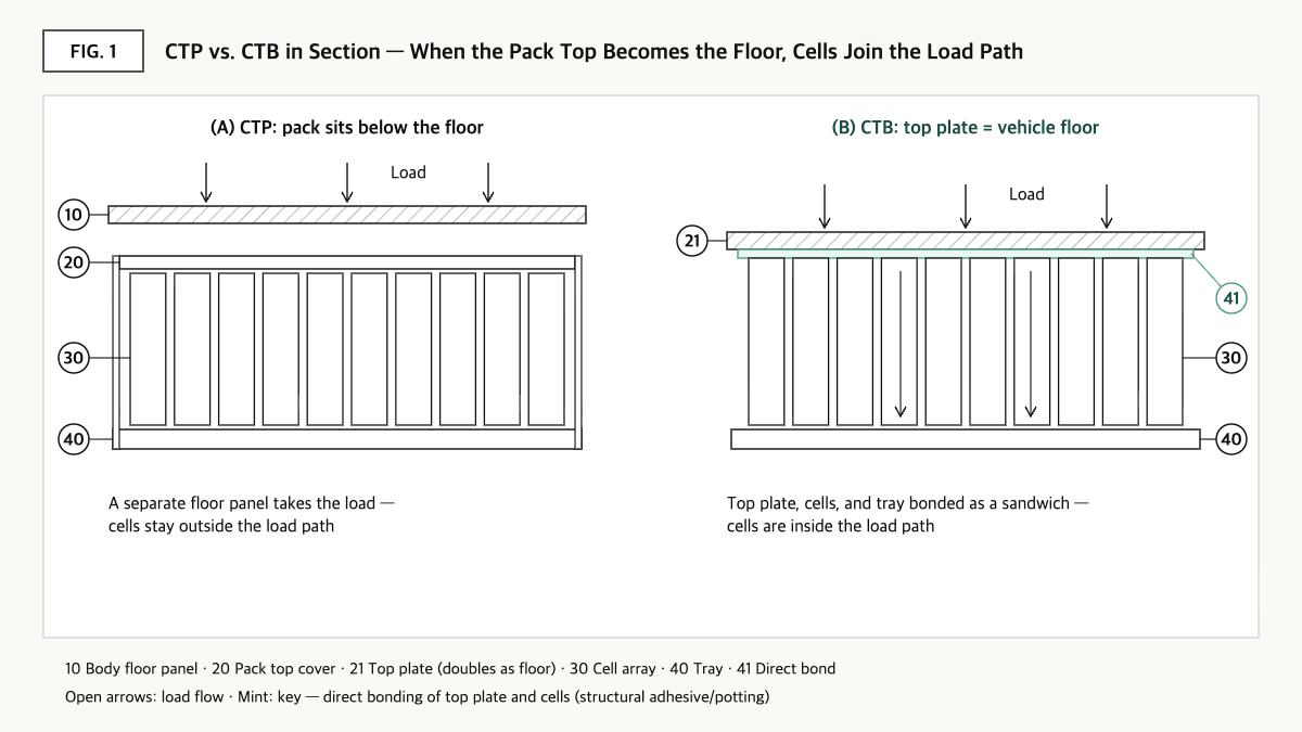
Source: reconstructed by the editorial team from BYD’s SEAL launch material (2023), the review by Liu et al. (2026), and the claims of US11962030B2.
This is exactly the principle of CTB. The top sheet is the pack top cover and also the cabin floor, the bottom sheet is the pack tray, and the core is the cell array. BYD states that the torsional stiffness of the SEAL sedan, which uses this structure, reaches 40,500 Nm/degree, and that it secured interior space while lowering the body height by about 15 mm[2]. Here the cell stores electricity and at the same time becomes the ‘core’ of the sandwich.
This principle creates three new requirements for cell design. First, because the cell casing becomes part of the load path, can stiffness and dimensional precision become important. Lithium-ion cells show anisotropy, meaning their mechanical properties differ by direction, and one analysis notes that elongated prismatic cells have a shape favorable for bearing loads along their length[1]. Second, the structural adhesive joining cells to the plates must transmit load and heat at the same time. One review summarizes that structural adhesives are required to have lap shear strengths exceeding 20 MPa and durability under thermal cycling from −40 to 80°C[1]. Third, venting paths must be designed so that thermal-runaway gases escape in a direction away from the cabin[1].
③ Comparison — CTM, CTP, CTB, CTC: What Is Gained and What Is Given Up
| Type | Structural concept | Volume utilization | Stiffness and other figures | Repair and recycling |
|---|---|---|---|---|
| Cell-to-Module (CTM) | 12–24 cells bundled into modules mounted in the pack | 40–50%[1] | — | Module-level replacement possible |
| Cell-to-Pack (CTP) | Cells integrated directly into the pack enclosure without modules | 60–70%[1] | About 40% fewer parts[1] | Mainly pack level |
| Cell-to-Body (CTB, BYD) | Sandwich structure in which the pack top cover doubles as the body floor | About 66%[1] | Torsional stiffness 40,500 Nm/degree (SEAL)[2] | Assessed as ‘bounded integration’ that retains some modularity[1] |
| Cell-to-Chassis (CTC, Tesla) | Pack as a structural member joined to front and rear cast subframes | Over 70%[1] | More than 70 parts removed from the floor structure[1] | Assessed as cell replacement impossible without separating from the body[1] |
Source: reconstructed by the editorial team from the review by Liu et al., Frontiers in Mechanical Engineering (2026)[1] and BYD’s SEAL European launch material[2]. Figures are those presented by each source, and measurement bases may differ by source.
What this table shows: Moving from CTP to CTB, volume utilization goes from 60–70% to about 66%, which is not a large difference[1]. This means the benefit of CTB lies in body stiffness (40,500 Nm/degree)[2] more than in space, and the price is paid in repairability and recyclability.
At this point, the roles of cell makers and automakers also diverge. CTP fit well with a model in which the cell maker designed and delivered up to the pack, but CTB and CTC cannot be separated from body design, so the structure inevitably increases the automaker’s control. The cell increasingly becomes ‘a part ordered to fit the body drawing.’
④ Patent Perspective — The Claim Boundary Drawn by One Line: ‘The Top Plate Is the Floor’
As an example in which the claim language of a structural pack can be confirmed, consider Tesla Inc’s US patent US11962030B2 (title: Integrated energy storage system). The applicant and current assignee is Tesla Inc; the priority date is 2019-11-21 (US provisional application 62/938,646), the filing date is 2020-11-20, it was published as US20210159567A1 (2021-05-27), and the grant date is 2024-04-16. According to Google Patents, the legal status is Active (anticipated expiration 2040-12-19), there are 31 granted claims, and continuation applications (US12456777B2, US20260031463A1) have followed[3].
Restating claim 1 element by element without reproducing the original wording gives the following.
| Claim 1 elements (restated) | Meaning for the scope of rights |
|---|---|
| (a) A plurality of cell arrays — each array is a line of cylindrical cells arranged in a common orientation | Cell-format limitation — claim 1 is narrowed to cylindrical cells |
| (b) A cooling channel formed near the cell arrays | Thermal management element — only its location is limited |
| (c) A potting material made of a resin compound encompasses the cell arrays and provides structural support and thermal protection | A limitation that ‘the filler is a structural member’ — the point distinguishing it from mechanical fastening |
| (d) A bottom surface supporting the cell arrays | Conventional element |
| (e) A top surface supporting the cell arrays | Conventional element |
| (f) The top surface is directly bonded to at least one cell array and forms the floor of a vehicle | A limitation fixing the integration of the pack top plate and the vehicle floor — the branching point of infringement analysis |
Source: reconstructed by the editorial team from the bibliographic data and claim structure of US11962030B2 on Google Patents (the original claim wording and drawings are not reproduced).
The axis of the scope of rights is (f). Even if cells are set in potting material, if the pack top plate sits below a separate vehicle floor, it may not literally satisfy (f). Conversely, if the top plate is bonded directly to the cells and doubles as the cabin floor, there is greater room for this limitation to be satisfied even if the cell arrangement differs somewhat.
Sketching design-around scenarios, the following could be considered: ⓐ using prismatic or pouch cells instead of cylindrical cells, ⓑ placing a gap or a separate member between the top plate and the cells to avoid ‘direct bonding,’ and ⓒ using mechanical fixing or non-structural filler instead of resin potting. The counterarguments, however, are strong. Independent claim 14 of the same patent claims a system combined with ‘a vehicle body that does not comprise a passenger floor component’ without limiting the cells to cylindrical ones (dependent claim 15 specifies cylindrical or rectangular cells), and independent claim 24 uses the broader term ‘energy module’ instead of cells[3]. In other words, switching cell format alone under ⓐ may not complete a design-around. Options ⓑ and ⓒ cut into the very stiffness gain CTB aims for, so the design-around cost may come back as a performance loss.
Adding one more perspective from this article: because these claims target not the cell itself but ‘the way the pack and body are joined,’ direct-infringement issues are likely to fall mainly on the party integrating the body and pack, and for cell suppliers they are likely to spread into indirect infringement or warranty issues under supply contracts. A cell maker’s FTO does not end with looking at cell claims alone.
Cross-check of similar patents: BYD describes in public materials a sandwich structure integrating the pack top cover with the body floor as CTB[2], so structures that conceptually overlap with (f) are being practiced by multiple companies. However, the numbers and claims of BYD’s corresponding CTB patents were not confirmed from the original text in this search.
⑤ Limits and Outlook
Optimistically, CTB integration can reduce battery-system mass by 10–15%[1] and greatly raise torsional stiffness[2], improving driving performance and interior space at the same time. From the cell’s point of view, as pack parts decrease, the quality of the cell itself translates directly into vehicle quality.
The opposing scenario is also clear. Cells bonded with adhesive cannot be removed non-destructively, so even a minor underbody impact could lead to replacing the entire pack, or even a total-loss judgment[1]. Cell recovery also becomes difficult at the recycling and second-life stages[1]. If repair costs and insurance premiums rise, the cost savings gained in manufacturing may be offset in cost of ownership.
A strategic alternative is ‘separable integration.’ The review lists reversible adhesives, designed debonding features, and variants that retain modularity as alternatives, while summarizing that each is a trade-off giving up some joint durability, structural efficiency, or degree of integration[1]. BYD being assessed as ‘bounded integration’ that retains some modularity is in the same vein[1]. For a cell maker, proposing bonding-surface specifications and debonding temperature conditions in the cell specification first could be a way to strengthen its negotiating position.
Action to check (planning/IP teams): If your cells go into a customer’s CTB or CTC design, check together with the customer whether that design satisfies the elements of independent claims 1, 14, and 24 of US11962030B2 (structural support by resin potting, direct bonding of the top plate to the cells, the top plate doubling as the floor, sealing against the body), and confirm whether the intellectual property indemnity clause in the supply contract covers body-integrated structures.
Items Requiring Verification
- The numbers, claims, and grant status of BYD-owned patents corresponding to the BYD CTB structure were not confirmed from the original text in this search.
- Whether the structural pack of Tesla’s production vehicles practices the claims of US11962030B2 was not checked.
- The volume utilization and mass reduction figures in Fig. 2 are values summarized by the review paper; the measurement conditions for individual vehicle models were not checked.
- The grant status in each country of the overseas family of US11962030B2 (based on PCT/US2020/061626) was not checked in this article.
Sources
- Liu et al., “A review of cell-to-body (CTB) battery-structure integration design for electric vehicles,” Frontiers in Mechanical Engineering, 2026-05-07, DOI 10.3389/fmech.2026.1825484. Link
- BYD, “BYD SEAL arrives in Europe Setting the Standard in Breakthrough Technology and Stunning Design,” 2023-09-01. Link
- Google Patents, US11962030B2 “Integrated energy storage system,” bibliographic data and claims (original checked 2026-09-23). Link
This article is a technology and patent trend commentary, not legal advice. Specific FTO judgments require professional review.
Related Reading