The default is to coat an electrode evenly with a single composition, but as fast charging and high loading converge, multilayer and gradient designs that split the composition between the separator side and the current-collector side are increasing. This article sets out why composition is varied through the thickness, and reads the claim boundary through LG Energy Solution’s granted patent claiming two graphite layers with different diffusion rates.
① What’s the Topic
A multilayer electrode is not a technology of “how many layers are stacked,” but one that assigns different jobs to the separator side, where ions arrive first, and the current-collector side, where they arrive later. And the patent fence, too, is drawn not around the number of layers but around the “ratio” of properties between layers.
Start with the industry context. Anode designers have long been caught between two goals. Active materials with high capacity fall short on charging performance, and those with good charging performance fall short on capacity. The common solution was to mix the two materials within one layer. LG Energy Solution’s patent specification, however, points out the limit of this approach: once mixed, the material with good charging performance cannot be sufficiently positioned at the anode surface, so lithium-ion diffusion is not smooth, and performance may deteriorate due to surface side reactions and byproducts[1].
The tension is fast charging. The larger the charging current, the more ions crowd at the electrode surface near the separator, and lithium plating tends to start there first. A study that divided a graphite anode into three layers, giving the top layer the highest porosity and the bottom layer the lowest, reported that this structure significantly suppressed lithium plating up to 4C charging[2]. This is why designs that vary composition through the thickness are increasing in both the laboratory and patents at the same time.
The question this article answers is this: Why vary composition through the thickness, and what changes could collide with rights that are already granted?
② Basic Principle — A Multilayer Electrode Is “a Supermarket With Fast Checkouts at the Entrance”
Picture a supermarket at rush hour. All customers (lithium ions) come in through one entrance (the separator side). Checkouts near the entrance are always crowded, and those farther inside are quiet. If every checkout runs at the same speed, long lines form at the entrance, and impatient customers leave their goods in the aisle and walk out. This corresponds to surface lithium plating. A smart store puts fast self-checkouts at the entrance and large-cart checkouts farther inside.
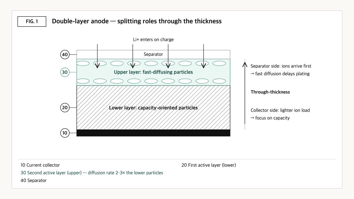
Source: reconstructed by the editorial team from the US11777080B2 specification and gradient-electrode research.
A multilayer anode follows the same logic. The upper layer (separator side), where ions arrive first, holds particles with a fast lithium-ion diffusion rate to take in the incoming ions quickly, and the lower layer (current-collector side), where the ion load is relatively small, holds high-capacity particles to preserve overall capacity. Mixed in one layer, the fast particles are scattered across the whole thickness; split into layers, they can be concentrated where they are needed.
Depending on what is varied, design variables branch in several directions. One can change the type and diffusion rate of the particles, change the porosity, or change the binder type or particle orientation. Here, the orientation index expresses, as an X-ray diffraction peak area ratio, how much graphite crystal planes lie in one direction. The patent specification uses artificial graphite with an orientation index of 12–14 and sets artificial graphite with an orientation index of 21.5 as a comparison[1]. A porosity gradient solves the same problem by reducing the ion concentration gradient in the electrolyte[2], and a particle gradient by raising the ion uptake speed of the particles themselves.
③ Comparison — Single-Layer Blend, Double-Layer Particle Design, Three-Layer Porosity Gradient
| Axis | Single-layer blend | Double-layer particle design (US11777080B2) | Three-layer porosity gradient (Yang et al. 2022) |
|---|---|---|---|
| Variable changed through thickness | None (uniform) | Particle type, diffusion rate, orientation index (claim 1 also includes binder)[1] | Porosity[2] |
| Separator side (upper layer) | Fast particles not sufficiently positioned at the surface[1] | Artificial graphite, diffusion rate 1.0–2.0×10⁻⁸cm²/s, orientation index 12–14[1] | Highest-porosity layer[2] |
| Collector side (lower layer) | — | Natural graphite, diffusion rate 5.0–7.0×10⁻⁹cm²/s[1] | Lowest-porosity layer[2] |
| Layer thickness in examples | — | Lower 60µm + upper 30µm (110µm total including 20µm copper foil)[1] | No sourced figure |
| Reported effect | Limited charging-performance improvement, surface side reactions[1] | Delayed onset of lithium plating in a 1.6C charging evaluation (vs. a single-layer blend comparative example)[1] | Lithium plating suppressed up to 4C; better rate capability and durability than 1-layer electrodes[2] |
Source: reconstructed by the editorial team from the US11777080B2 specification and claims[1] and Yang et al. (2022)[2].
What this table shows: The double-layer patent sets the upper-layer particles’ diffusion rate at 2–3 times that of the lower layer (e.g., 1.0–2.0×10⁻⁸ vs. 5.0–7.0×10⁻⁹cm²/s), while the porosity-gradient study solved the same aim from the pore side. Both approaches share the direction of “making the separator side faster”; they differ only in what they use to make it faster.
④ Patent Perspective — The Fence Is the “2–3×” Ratio, Not the Layers
The key patent is US11777080B2 (title: Negative electrode for secondary battery) held by LG Energy Solution. The applicant was LG Chem and the current assignee is LG Energy Solution. Its priority date is 2016-07-04 (Korean application 10-2016-0084358), its PCT filing date is 2017-07-04, it was published in the US (US20180287145A1) on 2018-10-04 and granted on 2023-10-03; its legal status on Google Patents is Active (anticipated expiration 2037-07-04), with 15 granted claims[1].
| Elements of claim 1 (restated) | Meaning for the scope of rights |
|---|---|
| (a) A negative electrode composed of a current collector, a first active material layer (first particles) on it, and a second active material layer (second particles) on that | Limits stacking order — the collector side is the first layer, the surface side the second |
| (b) The lithium-ion diffusion rate of the second particles is 2–3 times that of the first particles | Key limitation — defines the invention by the ratio between the two layers’ particles, not by absolute values |
| (c) The first particles are natural graphite, and the second particles are artificial graphite with an orientation index of 12–14 (orientation index being the XRD (004)/(110) peak area ratio) | Limits the material combination and even the measurement definition |
| (d) Each layer includes a binder and a conductive material, and the second binder is a copolymer of HFP with at least one of PVdF, CMC and SBR | Limits the upper-layer binder — but independent claim 15 lacks this element |
| (e) The content of the second particles is 30–90% of the total particles | Limits the relative weight of the two layers — absent from independent claim 15 |
| (f) Diffusion rates: first particles 5.0–7.0×10⁻⁹cm²/s, second particles 1.0–2.0×10⁻⁸cm²/s | Sets an absolute-value window in addition to the ratio |
Source: reconstructed by the editorial team from the claim structure of US11777080B2 (original claim wording and drawings not reproduced verbatim).
The most important point in reading this patent is that there are two independent claims. Claim 15 drops the upper-layer binder (HFP copolymer) element and the particle content (30–90%) element from claim 1, and consists only of the layered structure, the diffusion-rate ratio and absolute values, the natural/artificial graphite combination and the orientation index[1]. That means its scope of rights is correspondingly broader.
Design-around scenario (with counterargument): The commonly considered “change only the upper-layer binder” may avoid claim 1 but is likely to be ineffective against claim 15. On a literal reading, meaningful design-around axes are ① keeping the diffusion-rate ratio between upper and lower particles below 2× or above 3×, ② keeping the orientation index of the upper-layer artificial graphite outside 12–14, and ③ building the lower layer from a material other than natural graphite (e.g., a combination of two artificial graphites).
There is a counterargument. Diffusion rates may vary with measurement method and conditions, so a design that was out of range by your own measurement could come into range by the other party’s measurement. Also, where the boundary between two layers partly intermixes in simultaneous coating, interpretation of the element “the second layer is disposed on the first layer” could become the subject of a dispute. So if a design-around is chosen, it is advisable to keep records reproducing the measurement methods for diffusion rate and orientation index in line with the specification’s definitions.
Cross-check of similar patents: The study of a three-layer graphite electrode that divides the thickness by porosity (Yang et al., 2022) is non-patent literature solving the same aim with a different variable, and may become a reference in future novelty and inventive-step assessments of porosity-gradient claims[2]. On the manufacturing side, rights on the equipment that makes multilayer electrodes possible have also formed separately, such as the dual slot-die coater patent (US20250375790A1) that coats two layers at once.
⑤ Limits and Outlook
On the optimistic side, the value of through-thickness design rises as fast-charging demand grows. The ability to delay the onset of lithium plating merely by rearranging two existing graphites, without developing a new material[1], is an advantage that is easy to apply directly to mass-produced cells.
The counter-scenario is process and quality control. With two or more layers, per-layer thickness, loading and boundary intermixing must all be controlled, and deviation in one layer can shake overall performance. If the diffusion rate of anode materials themselves improves enough for a single layer to deliver sufficient charging performance, it may become hard to justify the extra cost of multilayer designs.
The strategic alternative is to choose “what to vary through the thickness” based not only on performance but also on measurability and the density of existing rights. Variables with large measurement scatter, such as particle diffusion rate, make both proving infringement and proving a design-around difficult, while variables that can be measured reproducibly, such as porosity or layer thickness, give relatively sharp claim boundaries. That is why IP staff should be involved at the design-variable selection stage.
Action to check (planning/IP teams): Organize your multilayer anode projects by per-layer material, diffusion rate, orientation index and binder, then compare them separately against US11777080B2 claim 1 and claim 15. In particular, for a “natural graphite lower layer + artificial graphite upper layer” combination, it is advisable to secure measurement records of the diffusion-rate ratio (2–3×) and the orientation index (12–14) first.
Items Requiring Verification
- The method used in the US11777080B2 specification to measure lithium-ion diffusion rate was not checked in detail this time.
- The charging-performance figures in the US11777080B2 examples were not cited because reading of the original table was uncertain; they are described only qualitatively.
- The claim composition and grant status of family patents, including the Korean priority application (10-2016-0084358), were not checked.
- Per-layer porosity values and electrode loading in Yang et al. (2022) could not be confirmed because the original paper was not accessed.
Sources
- Google Patents, US11777080B2 “Negative electrode for secondary battery,” bibliographic data, specification and claims 1–15 (original checked 2026-09-23). Link
- J. Yang, Y. Li, A. Mijailovic, G. Wang, J. Xiong, K. Mathew, W. Lu, B. W. Sheldon, Q. Wu, “Gradient porosity electrodes for fast charging lithium-ion batteries,” Journal of Materials Chemistry A, 2022 (abstract checked). Link
This article is a technology and patent trend commentary, not legal advice. Specific FTO judgments require professional review.
Related Reading
- [Patent Analysis] LG Energy Solution’s Dual Slot-Die Coater Patent (US20250375790A1) — The Scope of Rights Opened by Simultaneous Double-Layer Coating Through a Die-Lip Thickness Differential
- Fast-Charging Anode Material Patents — Why Coat Graphite Surfaces with Tungsten
- Silicon Anode Materials — Why Only Small Amounts Are Still Blended In: The Volume-Expansion Wall and 2026 Commercialization Trends