Among large prismatic cells, there are structures that place two or more electrode assemblies (jelly rolls) in a single can and connect them in parallel. This article explains why cell makers split the assembly into several instead of winding one large one, and how patents attach to the “binding part.”
① What’s the Topic
The multi-jelly-roll prismatic cell is a compromise between a manufacturing constraint, “it is hard to wind large,” and an energy-density constraint, “the parts that bind them take up space.” That is why the decisive point of this structure lies not in the electrodes but in the connection that binds the assemblies into one.
Looking at the industry, prismatic cell capacity is growing in both EVs and energy storage systems (ESS). An analysis of ESS cells assesses that larger cells are harder to produce by winding, and that cells of 684 Ah and above are produced only by stacking (Z-stacking)[1]. For manufacturers with winding equipment and process know-how, “putting several wound assemblies into one can” becomes one path to higher capacity. Indeed, the specification of CATL’s current-collecting component patent describes an embodiment that connects the tabs of two side-by-side electrode assemblies to both sides of a single current-collecting component[2].
The source of tension lies in the connection. With multiple assemblies, a current-collecting component is needed to gather the tabs of each assembly and route them to the terminal, and energy density falls by the space needed to fold this component in. The patent also cites as background that, when the component is folded after welding the tabs, it may deform and press against and damage the electrode assembly[2].
So the question this article answers is: why put several electrode assemblies into one can, what problems arise when doing so, and where have patents put up their fences?
② Basic Principle — One Thick Quilt Versus Two Thin Quilts
Folding one thick cotton quilt neatly into a wardrobe is harder than it sounds. The thicker the layers, the more the folded lengths of the outer and inner sides differ, causing wrinkles and losing shape. Folding two thin quilts separately and placing them side by side is much easier. In exchange, you need a string to tie the two together so they do not shift, and the knot takes up a little space in the wardrobe.
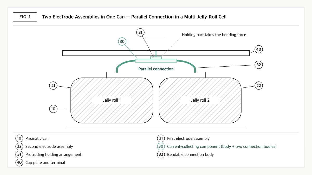
Source: reconstructed by the editorial team from the specifications of US11417935B2 and US8557422B2.
Wound electrode assemblies are similar. To increase capacity with a single assembly, the electrodes must be wound longer and in more layers, and the thicker the assembly, the harder the winding process is to control. Splitting the assembly into two makes each one thinner and tends to shorten the distance electrolyte must soak in. In return, a current-collecting component is needed to connect the two assemblies in parallel, along with space to gather and fold the tabs, and a new task arises of managing capacity and resistance differences between the two assemblies.
The idea of “multiple assemblies in one case” is not new in itself. LG Chem (now LG Energy Solution) filed, with a 2006 priority, and obtained a grant for a high-capacity secondary battery structure that places two or more unit cells in one battery case and wraps them with a long separator sheet[4]. What is new is not “splitting” but “how to bind the split parts without space loss or damage.”
This article’s perspective in one line: a multi-jelly-roll cell is not a “technology for making one cell bigger” but a “technology for making several small assemblies look like one cell.” That is why the center of rights and competitiveness shifts from the electrodes themselves to the connection that binds the assemblies.
③ Comparison — Single Large Assembly, Multi-Jelly-Roll, and Stacked
| Item | Single large jelly roll | Multi-jelly-roll (2 or more in parallel) | Stacked |
|---|---|---|---|
| Assembly difficulty when scaling up | High — larger cells assessed as harder to wind[1] | Medium — each assembly can be wound thin | The method adopted for large cells[1] |
| Electrolyte wetting distance | Long | Tends to shorten per assembly | Depends on electrode size |
| Internal connection parts | Few | Parallel current-collecting component between assemblies required[2] | Collective welding of many tabs required |
| Sources of space loss | Winding curvature | Curvature + tab folding and collecting-component space[2] | Tab gathering area |
| New management tasks | Winding tension and alignment | Capacity/resistance matching between assemblies, preventing damage during folding[2] | Stacking alignment and speed |
Source: reconstructed by the editorial team from an EVreporter analysis[1] and the specification of US11417935B2[2]. Because no items have published figures, the entire table is a qualitative comparison.
What this table shows: The multi-jelly-roll lowers the winding difficulty of a single large assembly but creates new costs in connection parts and tab-folding space. The moment this structure is chosen, the focus of design and patents shifts from “the electrodes” to “the connection.”
④ Patent Perspective — Not “How Many to Put In” but “Where the Force Is Taken When Folding”
The key patent is CATL’s US11417935B2 (title: Component for collecting current and battery). The original applicant is Contemporary Amperex Technology Co Ltd, and the current assignee is shown as Contemporary Amperex Technology (Hong Kong) Limited; the priority date is 2018-01-16, the filing date 2019-01-10, and the grant date 2022-08-16. Its legal status is Active (anticipated expiration 2039-06-17)[2]. The Chinese priority basis CN108258180B (granted 2020-09-29) and European EP3512003B1 and EP3787099B1, among others, are granted in the same family[3].
| Elements of claim 1 (paraphrased) | Meaning for the scope of rights |
|---|---|
| (a) A battery including an electrode assembly and a current-collecting component electrically connecting it to the outside | Subject limitation — the number of assemblies is not limited in claim 1 |
| (b) The component consists of an introducing body and a connection body bendably connected to the introducing body | Two-part structure of “a folding connection body + a fixed body” |
| (c) The introducing body includes a holding arrangement and an inner connecting structure linking the holding arrangement to the connection body | Limitation on the internal configuration of the body |
| (d) The holding arrangement protrudes away from the assembly and is configured to be fixed when the connection body is bent | Key limitation — a structure that diverts bending stress to a fixing point instead of the assembly |
| (e) The holding arrangement and the inner connecting structure extend along mutually parallel planes, and the plane of the inner connecting structure is substantially perpendicular to the protruding direction | Geometric arrangement limitation |
| (f) The assembly-facing surface of the holding arrangement is recessed in the protruding direction relative to that of the inner connecting structure, forming a hollow space between them | Shape limitation — a main checkpoint for design-around |
| (g) The connection body is directly connected to a tab of the assembly, and the introducing body is electrically connected to the outside | Electrical path limitation |
Source: reconstructed by the editorial team from the bibliographic data and claim structure of US11417935B2 published on Google Patents (original claim wording and drawings not reproduced).
What stands out is that claim 1 does not limit the number of assemblies. The configuration in which two connection bodies sit on both sides of the introducing body and connect respectively to the tabs of two side-by-side assemblies is in the dependent claims and the specification[2]. The specification explains that the operator bends the connection body while holding the holding arrangement with a clamping tool, so that bending stress is transferred to the tool rather than to the assembly, and presents the effect of raising energy density by reducing the internal space occupied by the component after bending[2]. The core effect of the rights can be summarized as lying not in “putting in several” but in “where the force is taken when folding.”
Design-around scenario (with counterargument): Approaches that (a) bend while fixing the connection body itself or the cap plate side with a jig, without a protruding holding arrangement, (b) use a holding arrangement but a flat structure without the recessed hollow space of (f), or (c) weld tabs to a pre-formed collecting component without bending, may not satisfy some elements of claim 1. There are counterarguments too. Options (a) and (c) must solve again, by other means, the “damage to the assembly during folding” or “space loss” problems this patent addressed, and in option (b), equivalence could be disputed over whether the shape difference is a substantial functional difference. If European production is under consideration, the claims of EP3512003B1 and EP3787099B1 may differ from the US claims, so freedom to operate (FTO) judgments should be made against each country’s granted claims.
Similar-patent cross-check: US8557422B2, with LG Energy Solution shown as assignee (priority date 2006-06-05, grant date 2013-10-15, Active, anticipated expiration 2028-05-04), claims a structure in which two or more unit cells, each with terminals in opposite directions at both ends, are stacked or arranged in a plane in one case and all wrapped by a long separator sheet[4]. Because the concept of “several assemblies in one case” has been protected for this long, new rights disputes are more likely to arise in the details of connection structures than in the concept.
⑤ Limits and Outlook
Optimistically, the multi-jelly-roll may continue to be used as a realistic path to larger cell capacity while leveraging existing winding equipment and process experience. CATL announced that its 587 Ah ESS cell has an inherent failure rate an order of magnitude lower than laminated cells[5], a company claim suggesting that winding-type processes remain a competitive option even for large cells.
There is also a counter-scenario. Assemblies bound in parallel share the influence of “the weakest assembly.” If capacity or resistance differs between assemblies, current does not divide evenly, and the degradation of one assembly may drag down the performance of the whole cell. As weld points in the connection increase, so do potential defect points. Also, a shift to stacking is observed in the range where cells get even larger[1], so the multi-jelly-roll is unlikely to be the answer for every capacity range.
The strategic alternative is to include assembly matching and connection inspection in the cell specification. Specifying, as supplier quality requirements, a process that sorts and pairs the assemblies going into one can by capacity and resistance, and inspection criteria for tab bends and collecting-component welds, can reduce the weaknesses of the multi-jelly-roll structure to a manageable range.
Action to check (planning/IP teams): Compare the current-collecting component drawings of the multi-jelly-roll cell under development or procurement one-to-one with the (d) protruding holding arrangement and (f) recessed hollow space requirements of claim 1 of US11417935B2, and depending on the production region, also check the granted claims of EP3787099B1 and CN108258180B.
Items Requiring Verification
- Which mass-produced large prismatic cell models at home and abroad use a multi-jelly-roll structure was not confirmed from official materials.
- Whether the claim scope of EP3512003B1 and EP3787099B1 is the same as US claim 1 was not compared against the originals.
- Whether US11417935B2 has actually been applied to CATL production cells has not been confirmed.
- No public data quantitatively comparing the energy density and defect rates of multi-jelly-roll and single-assembly designs was found, so the comparison table is qualitative.
- The “failure rate versus laminated cells” of CATL’s 587 Ah cell is a company announcement, and whether this cell uses a multi-jelly-roll structure was not checked.
Sources
- R. Bollini, “Next Generation BESS Technologies using 392Ah / 587Ah / 684Ah LFP Cells,” EVreporter, 2026-07-14. Link
- Google Patents, US11417935B2 “Component for collecting current and battery,” bibliographic data, claims, and specification (original checked 2026-09-23). Link
- Google Patents, CN108258180B bibliographic data and family information (checked 2026-09-23). Link
- Google Patents, US8557422B2 “High capacity battery cell employed with two or more unit cells” (checked 2026-09-23). Link
- “CATL Launches Mass Production of 587Ah Cell,” Battery Energy Storage System News, 2025-06-20. Link
This article is a technology and patent trend commentary, not legal advice. Specific FTO judgments require professional review.
Related Reading