Heat does not flow equally in all directions inside a battery cell. It flows well along the electrode plane and poorly through the thickness. This article explains why this “directional difference” changes which face of the cell a cooling plate should be attached to.
① What’s the Topic
A cell’s thermal conductivity differs by tens of times depending on direction. In a study that measured a 20 Ah LFP pouch cell, the in-plane thermal conductivity was 26.6 W/(m·K) and the through-plane value was 0.52 W/(m·K), a difference of about 51 times[1]. Cooling-face selection should start from this ratio.
Looking at the industry, cooling structures for EV packs and energy storage systems (ESS) often attach a cooling plate to the large face or bottom face of the cell. Attaching to a large face gives a large contact area and simple assembly. As fast charging becomes widespread, the heat that a single cell must release in a short time is also increasing.
The source of tension is that the “large face” is not necessarily the “face where heat escapes easily.” To remove heat through the large face, heat must travel through the cell thickness, the direction with the poorest conduction. In an experiment on pouch cells, surface cooling lost far more usable capacity than tab cooling under high-rate discharge, and its degradation rate after 1,000 cycles was about three times faster[3].
So the question this article answers is: why does thermal conduction inside a cell differ so much by direction, and how does that difference change the choice of cooling face?
② Basic Principle — A Highway Versus an Alley Full of Traffic Lights
Think of the inside of a cell as a thick stack of paper or a multi-layer sandwich. The positive current collector (aluminum foil), positive active material layer, separator, negative active material layer, and negative current collector (copper foil) repeat in many layers. Metal foils are continuous plates that conduct heat well, so for heat flowing along the plane they are an unobstructed highway. To travel through the thickness, however, heat must pass through active material, electrolyte-soaked separator, and interlayer interfaces every time it crosses a layer. It is like an alley lined with traffic lights.
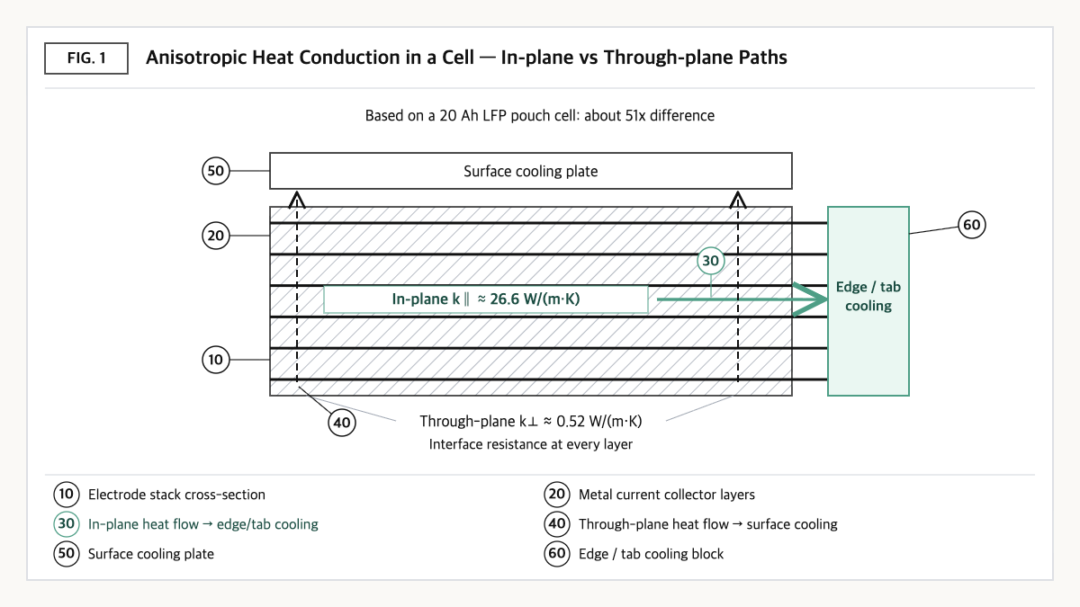
Source: reconstructed by the editorial team from the measurements and experiments of Lin et al. (2022) and Hunt et al. (2016).
The principle is the same for cylindrical cells. Because the electrodes are wound, heat must keep crossing layers in the radial direction, while in the axial direction it follows the current collectors. A study that measured 18650 and 26650 LFP cylindrical cells reported that radial thermal conductivity is about two orders of magnitude lower than axial[2].
This difference carries through to cooling results. Surface cooling receives heat over a large area, but heat must pass the through-plane thermal resistance from the cell center to the surface. As a result, a temperature gradient forms through the cell thickness, and hotter layers, with lower reaction resistance, draw more current. The experimental study above explained that such perpendicular temperature gradients lead to local current concentration and faster degradation. Tab cooling, by contrast, goes through a narrow cross-section but uses the well-conducting in-plane path, so temperature within the electrode plane stayed relatively uniform[3].
This article’s perspective in one line: the question when choosing a cooling face is not “which face is largest” but “in which direction does heat want to run.” Because through-plane thermal resistance grows with cell thickness, the thicker the cell, the more likely the answer shifts from the surface toward the edge (tab).
③ Comparison — Directional Thermal Conduction and Cooling Outcomes
| Item | In-plane / axial (path to the tab or edge) | Through-plane / radial (path to the large face) | Source |
|---|---|---|---|
| 20 Ah LFP pouch thermal conductivity | 26.6 W/(m·K) | 0.52 W/(m·K) | [1] |
| 18650 / 26650 LFP cylindrical conduction | Relatively high (baseline) | About two orders of magnitude lower than axial | [2] |
| Cooling method using this direction | Tab cooling | Surface cooling | [3] |
| Usable capacity loss at high rate (10-minute discharge) | 1.2% | 9.2% | [3] |
| Degradation rate after 1,000 cycles | Baseline | About 3 times that of tab cooling | [3] |
Source: reconstructed by the editorial team from Lin et al. (2022, Batteries & Supercaps), Drake et al. (2014, Journal of Power Sources), and Hunt et al. (2016, Journal of The Electrochemical Society). Because the results come from different cells and conditions, values across rows are not directly compared.
What this table shows: The difference between the direction in which heat flows well and the direction in which it flows poorly is about 51 times for the pouch cell[1], and cooling that follows this difference (tab cooling) showed smaller high-rate capacity loss and slower long-term degradation than cooling that goes against it (surface cooling)[3]. The position of the cooling plate should be decided together with the directionality of the cell’s internal properties.
④ Patent Perspective — A Claim That Widens the Tab to Bring the “In-Plane Path” to the Cooling Plate
As a representative patent that puts anisotropy to use in design, consider GM’s US10680297B2 (title: Tab cooling for pouch cell). The original applicant and current assignee is GM Global Technology Operations LLC; the priority date is 2017-07-24, the filing date 2017-07-24, and the grant date 2020-06-09. Its legal status is shown as Active (anticipated expiration 2038-03-01). Chinese CN109301378B and German DE102018117784B4 are granted in the same family[4]. The specification targets heat rejection from pouch cells during fast charging and describes a configuration that uses both in-plane and through-plane heat transfer.
| Elements of claim 1 (paraphrased) | Meaning for the scope of rights |
|---|---|
| (a) A cooling plate defining a channel that receives coolant | Cooling-means limitation — liquid coolant channel type |
| (b) An electrode stack of stacked electrodes, each having a main electrode layer and an electrode tab protruding from it, in thermal communication with the cooling plate | Subject limitation — stacked electrode structure |
| (c) A heat-rejecting lead tab coupled to the plurality of electrodes | Gives the electrical lead-out part a heat-rejection role |
| (d) The heat-rejecting lead tab covers not only the tab area of the electrode tab but also the area of the main electrode layer, facilitating heat transfer from the stack to the lead tab | Key limitation — an extended lead tab covering “the electrode face,” not “only the tab” |
| (e) The electrodes include an innermost electrode and an opposite outermost electrode | Reference for arrangement in the stacking direction |
| (f) The lead tab consists of a main lead body and a heat-rejecting protrusion, the protrusion covering the tab area of the electrode tab | Lead-tab shape limitation |
| (g) The cooling plate is coupled to the main lead body | Cooling plate–lead tab coupling limitation — a main checkpoint for design-around |
Source: reconstructed by the editorial team from the bibliographic data and claim structure of US10680297B2 published on Google Patents (original claim wording and drawings not reproduced).
The gist of this claim is that it solves the weakness of tab cooling, namely that “the tab cross-section is narrow, so heat hits a bottleneck,” by widening the lead tab to cover the electrode face. It is natural to read the scope of rights as attaching not to the whole concept of tab cooling, but to the specific structure of the extended lead tab in (d) and the coupling relationship in (g).
Design-around scenario (with counterargument): Structures in which (a) the lead tab does not cover the main electrode layer area and cools only the electrode tab region, or (b) the cooling plate is coupled not to the main lead body but to the cell enclosure or a separate heat-transfer member, may not satisfy (d) or (g). There are counterarguments, however. Option (a) keeps the tab cross-section bottleneck and may lose cooling performance, and in option (b), if an intermediate member effectively performs the same function, equivalence could be disputed. In addition, other rights holders have granted patents in the tab-cooling field, so avoiding one patent does not secure freedom to operate (FTO).
Similar-patent cross-check: Qdot Technology’s US12476299B2 (Tab cooling for batteries, priority date 2020-05-11, grant date 2025-11-18, Active) claims a configuration that bends the terminals coupled to collectors of two different materials into contact with adjacent terminals to form pairs, and places a heat sink within the elongate channels formed between the flat terminal pairs to remove heat directly from the terminals[5]. If the GM patent is “extending the lead tab inside the cell,” the Qdot patent is “using the space between terminals outside the cell,” an example of the same anisotropy being protected at a different layer.
⑤ Limits and Outlook
Optimistically, as fast-charging demand grows, tab and edge cooling that uses the in-plane path may be considered more often as a complement to surface cooling, because the differences in capacity loss and degradation under high-rate conditions are clear, as the experimental results show[3].
There is also a counter-scenario. A tab is an electrical path before it is a thermal path. Attaching a cooling plate to a tab requires an interface that is both electrically insulating and thermally conductive, and the tab itself is a part that generates heat from current. Also, as cells become longer and wider, the in-plane path itself becomes longer, so the advantage of tab cooling may shrink with cell size.
The strategic alternative is to combine in-plane and through-plane paths according to cell shape, rather than picking a single cooling face. The starting point is to request directional thermal property data from suppliers from the cell selection stage and to enter anisotropic values instead of isotropic ones into thermal analysis models. The measurement study also stresses that capturing anisotropy is important for accurate thermal simulation[1].
Action to check (planning/IP teams): If your pack’s cooling structure removes heat through tabs or lead tabs, compare that structure one-to-one with the (d) extended lead tab and (g) cooling plate–main lead body coupling requirements of claim 1 of US10680297B2, and if it uses the external terminal side, compare it with US12476299B2 as well.
Items Requiring Verification
- The thermal conductivity values in the text are measurements of a specific 20 Ah LFP pouch cell (100% SOC); values for large prismatic cells or other chemistries were not checked.
- Whether US10680297B2 has been applied to GM’s production vehicles has not been confirmed.
- Only the gist of claim 1 of US12476299B2 was checked; its dependent claims and the grant status of European and Chinese counterparts were not reviewed.
- The comparison between tab cooling and surface cooling (capacity loss, degradation rate) comes from experiments on a specific pouch cell; whether it applies directly to other cell formats has not been confirmed.
Sources
- J. Lin, H. N. Chu, C. W. Monroe, D. A. Howey, “Anisotropic Thermal Characterisation of Large-Format Lithium-Ion Pouch Cells,” Batteries & Supercaps (2022). Link
- S. J. Drake et al., “Measurement of anisotropic thermophysical properties of cylindrical Li-ion cells,” Journal of Power Sources 252 (2014) 298–304. Link
- I. Hunt, Y. Zhao, Y. Patel, G. J. Offer, “Surface Cooling Causes Accelerated Degradation Compared to Tab Cooling for Lithium-Ion Pouch Cells,” Journal of The Electrochemical Society 163(9) (2016) A1846–A1852. Link
- Google Patents, US10680297B2 “Tab cooling for pouch cell,” bibliographic data and claim 1 (original checked 2026-09-23). Link
- Google Patents, US12476299B2 “Tab cooling for batteries,” bibliographic data (original checked 2026-09-23). Link
This article is a technology and patent trend commentary, not legal advice. Specific FTO judgments require professional review.
Related Reading