A composite current collector replaces copper or aluminum foil with a thin polymer film coated with metal on both sides. This article centers on the point that both its strengths — lighter weight and an advantage under extreme conditions such as nail penetration — and its weakness — harder tab welding — come from one source: the insulating polymer layer in the middle.
① What’s the Topic
The safety effect and the welding challenge of composite current collectors come from the same cause: the middle polymer layer that does not conduct electricity through its thickness. Because the advantage and the disadvantage cannot be separated, the center of gravity of patents in this field is also shifting from ‘the material’ to ‘the structure that draws current out.’
Start with the industry situation. A current collector is the metal foil that supports the electrode active material while collecting electrons and delivering them outside. Copper foil is typical for the anode and aluminum foil for the cathode. Since the current collector delivers no capacity, if the same role can be performed more lightly, the cell’s energy density per weight rises. This is where the composite current collector emerged: a ‘metal-polymer-metal’ sandwich structure with thin metal layers on both sides of a polymer film such as polyethylene terephthalate (PET).
A 2025 review summarizes that this sandwich-type composite copper foil significantly reduces the weight of the current collector and raises energy density, and that the middle polymer layer is insulating and flexible in the transverse direction, blocking heat diffusion and alleviating expansion stress[1]. There are two sources of tension. The same review names the weak bonding force between copper and polymer as a key challenge[1], and a 2026 study points out that the bonding mechanism between multi-layer metal-thermoplastic current collectors and tabs remains unclear and that the welding process is cumbersome[3].
So the question this article seeks to answer is this: By what principle does a composite current collector gain lightness and safety, and through what structures do patents try to solve the welding problem that comes as its price?
② Basic Principle — ‘Plywood Clad with Steel Plates’ Instead of a Log Bridge
Think of conventional metal foil as a bridge made from a single log. It is sturdy, and since it is the same wood wherever you cut it, joining pieces (welding) is easy. A composite current collector is a bridge made of light plywood with thin steel plates attached to both sides. Electricity flows along the steel plates (metal layers), and the plywood (polymer layer) holds the shape. Because plywood is much lighter than metal, a bridge of the same area can be made lighter. Indeed, a related patent specification explains that the density of the insulation layer is generally lower than that of metal, which can improve energy density per weight[4].
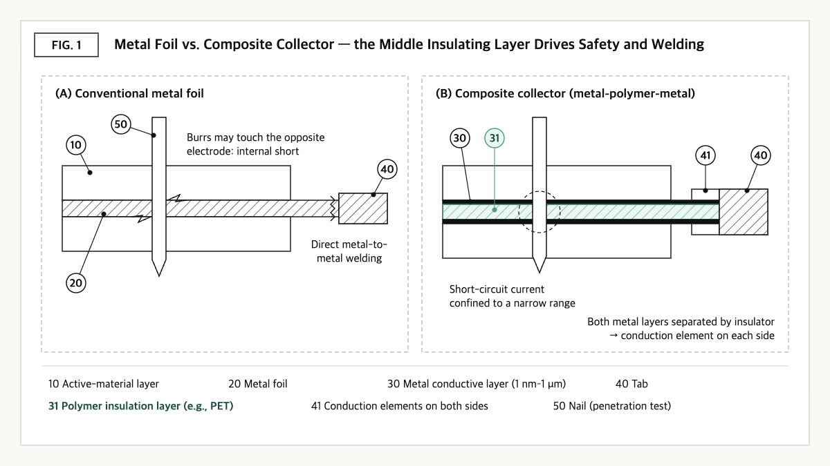
Source: reconstructed by the editorial team from Yao et al. (2023), Chen et al. (2026), and the specifications of US11539050B2 and US11233244B2.
The safety effect shows up in extreme situations such as nail penetration. Conventional metal foil easily forms burrs (torn metal slivers) when pierced by a nail, and if these burrs directly contact the opposite electrode, they can lead to an internal short circuit[5]. In a composite current collector, the metal layer is as thin as a few nanometers to 1 micrometer and the middle is an insulator, so, according to the applicant, it can be designed so that even if a short occurs, the range through which current flows is confined narrowly[4]. A study testing a cathode current collector with ultrathin aluminum on both sides of a PET film also reported that the temperature rise of the entire cell slowed during the nail penetration test[2].
The problem arises when connecting the end of the bridge to land (the tab). A log can simply be joined as is, but a plywood bridge must connect each of its two steel plates to land. According to an ultrasonic welding study, a composite current collector is joined not by the middle PET layer being pushed aside first so that metals touch, but through a complex sequence: initial adhesive bonding → gradual collapse of the laminated structure → a transition from mechanical interlocking to atomic diffusion[3]. The very layer that blocks current to protect safety becomes an obstacle at the moment current must be drawn out.
③ Comparison — Conventional Metal Foil vs. Composite Current Collector
| Item | Conventional metal foil (copper/aluminum) | Composite current collector (metal-polymer-metal) |
|---|---|---|
| Structure | Single metal layer (qualitative) | Metal layers on both sides of a polymer film such as PET[1][2] |
| Weight and energy density | Baseline | Significantly reduces current-collector weight, raising energy density[1] / insulation layer density lower than metal[4] |
| Metal-layer conditions (example from patent claim) | — | Thickness 1 nm–1 μm, room-temperature sheet resistance 0.08–8.4 Ω/□ (US11539050B2 claim 1)[4] |
| Behavior under nail penetration | Burrs may contact the opposite electrode and cause an internal short[5] | Reported to slow whole-cell temperature rise (PET-Al)[2] / design confining short-circuit current to a point range[4] |
| Tab welding | Direct metal-to-metal joining (qualitative) | PET layer is not displaced first, making joining complex; tensile strength drops when the structure collapses[3] |
| Interface challenge | — | Weak bonding force between copper and polymer[1] |
Source: reconstructed by the editorial team from Dun et al. (2025)[1], Yao et al. (2023)[2], Chen et al. (2026)[3], and the specifications of US11539050B2[4] and US11233244B2[5].
What this table shows: There are reports that composite current collectors outperform metal foil in weight and nail-penetration behavior[1][2], but they also bring in two new challenges: welding and interfacial bonding[1][3]. This means a material swap alone is not enough; process and structural design must follow.
④ Patent Perspective — A Two-Tier Fence of Material Claims and ‘Current-Extraction Structure’ Claims
When reading the rights in this field, two tiers should be separated. The first is claims that set the conditions of a cell using a composite current collector; the second is claims that set the connection structure that draws current from that collector. Two US patents of CATL (Contemporary Amperex Technology) illustrate this distinction well.
The first is US11539050B2. Priority date 2017-01-12, filing date 2017-11-30, grant date 2022-12-27, current assignee CATL’s Hong Kong entity (Contemporary Amperex Technology (Hong Kong) Ltd), legal status Active (adjusted expiration expected 2037-11-20), with 10 granted claims[4]. Restated element by element, claim 1 reads as follows.
| Elements of claim 1 (restated) | Meaning for the scope of rights |
|---|---|
| (a) A battery comprising a positive electrode plate, a separator, and a negative electrode plate | The claimed subject is a ‘battery,’ not the current collector alone — the cell maker becomes the direct practicing entity |
| (b) The current collector of the positive and/or negative electrode plate consists of an insulation layer and a conductive layer on it; the insulation layer bears the conductive layer, the conductive layer bears the active-material layer, and the conductive layer is on at least one surface of the insulation layer | Limitation of the basic composite-collector structure |
| (c) The conductive layer has a room-temperature sheet resistance of 0.08–8.4 Ω/□ and a thickness of 1 nm–1 μm | Numerical limitation of conductive-layer properties and thickness |
| (d) The conductive layer is a single layer of a material selected from aluminum, copper, titanium, nickel-copper alloy, aluminum-zirconium alloy, and combinations thereof | Material-group and ‘single layer’ limitation |
| (e) The product of the battery’s internal resistance r and theoretical capacity Cap is 126–384 Ah·mΩ, and Cap is 3.2–48 Ah | A limitation fixing the cell-level resistance × capacity relationship and capacity range — the boundary of applicable cell specifications |
Source: reconstructed by the editorial team from the bibliographic data and claim structure of US11539050B2 on Google Patents (original claim language and drawings not reproduced verbatim).
The axis of the scope of rights is (e). Claim 1 is literally limited to batteries with a theoretical capacity of 3.2–48 Ah, so for cells with capacities outside this range, a different conclusion may be reached at least in the literal-infringement analysis of claim 1. Based on this, design-around scenarios that could be examined include (i) cell specifications outside the capacity range, (ii) configuring the conductive layer as multiple layers rather than a single layer (e.g., a protective layer on the metal layer), and (iii) designing the conductive layer outside the sheet-resistance and thickness ranges.
The counterarguments are strong, however. Search results indicate that the same applicant holds several US patents in the ‘Current collector, electrode plate …’ line with a 2017-12-05 priority date (e.g., US10910652B2, US11024854B2, US11177479B2), so even if claim 1 alone is avoided, other family patents may cover the scope along different axes. Whether the ‘multiple layer’ configuration in (ii) falls within the range of equivalents also requires case-by-case judgment.
The second fence is directly tied to the welding problem. CATL’s US11233244B2 (priority date 2017-11-22, filing date 2020-02-28, grant date 2022-01-25, Active, adjusted expiration expected 2038-09-04, 13 claims) claims an electrode assembly with first and second conduction elements, each connected to the uncoated portion of the conduction layers on the two sides of an insulation substrate, arranged so that during winding the conduction elements sit between the stacked current guide portions formed by these uncoated portions[5].
The specification cites as its problem that connecting the conduction layer directly to the current collection member yields poor conduction and readily causes local overheating[5]. From a similar-patent cross-check perspective, this is a right that bypasses the intrinsic limit of composite current collectors — that the metal layers on both sides are electrically separated by the insulation layer — through ‘a structure that attaches a separate conductor to each side.’ For late entrants seeking to use composite current collectors, such extraction-structure claims may become a trickier gate in freedom to operate (FTO) review than the material claims.
⑤ Limits and Outlook
On the optimistic side, the fact that higher energy density through a lighter current collector[1] and slower temperature rise under nail penetration[2] are possible at the same time is likely to make this an attractive option in cell designs required to deliver both energy density and safety.
There is also a counter-scenario. The strength of composite current collectors comes from ‘the thin metal layer,’ but that same thinness may work against high-current extraction and welding reliability. The result that when the laminated structure collapses during ultrasonic welding, electrical connection is achieved but tensile strength drops[3], means additional long-term reliability verification is needed in vehicle environments with heavy vibration and shock. If the copper-polymer interfacial bonding problem[1] carries over into mass-production yield, the cost advantage could also be offset.
As a strategic alternative, an approach of developing and securing rights to material adoption and tab-extraction structure as a single package can be proposed. Even if the composite-collector material is sourced externally, the tab connection structure and welding conditions should be designed independently to fit one’s own process, with conflicts with prior rights checked at that stage.
Action to check (planning/IP teams): Compare the theoretical capacity, internal resistance, and conductive-layer configuration (single/multiple layers, thickness, sheet resistance) of the cell being considered for a composite current collector against the numerical ranges of claim 1 of US11539050B2, and separately check whether the tab connection method overlaps with the ‘conduction elements on both sides’ configuration of US11233244B2.
Items Requiring Verification
- For CATL’s patents with a 2017-12-05 priority date, such as US10910652B2, US11024854B2, and US11177479B2, only the bibliographic data in search results was checked; the content of each claim was not reviewed in this article.
- Mass-production cells and vehicle models using composite current collectors, cost per kg, and specific weight reduction (%) versus conventional metal foil could not be confirmed from public sources, so no figures were included.
- The Chinese and European family members of US11539050B2 and US11233244B2 and their maintenance status in each country were not separately checked.
Sources
- Xueyang Dun et al., “Composite copper foil current collectors with sandwich structure for high-energy density and safe lithium-ion batteries,” Energy Storage Materials 74, 2025 (103936). Link
- Wangbing Yao et al., “Polyethylene terephthalate-based cathode current collectors coated by ultrathin aluminum metal layers for commercial lithium-ion batteries with high security and long-term cycling stability,” Journal of Alloys and Compounds 941, 2023. Link
- Qi Chen et al., “Ultrasonic Welding of Multi-layer PET-Al Composite Current Collector and Al Tab: Joining Mechanism and Resistance Analysis,” Journal of Materials Engineering and Performance, 2026. Link
- Google Patents, US11539050B2 “Current collector, electrode plate and battery containing the same, and application thereof,” bibliographic data, specification, and claim 1 (original checked 2026-09-23). Link
- Google Patents, US11233244B2 “Electrode member, electrode assembly and rechargeable battery,” bibliographic data, specification, and claim 1 (original checked 2026-09-23). Link
This article is a technology and patent trend commentary, not legal advice. Specific FTO judgments require professional review.
Related Reading
- Electrode Tab Design — The Hidden Variable That Determines Internal Resistance
- [Patent Analysis] Electrode Tab-Lead Weld Inspection: X-ray + Deep Learning (TechDial) vs. Ultrasonic + AI (LG Energy Solution) Head-to-Head
- Thermal Runaway Propagation Blocking Patents — How to Keep Fire From Spreading to the Neighboring Cell