The lid of a cylindrical cell (the cap assembly) holds layered safety devices that respond to different signals: current, temperature, and pressure. This article explains what the CID, PTC, and vent each guard against, in what order they operate, and where the scope of rights of the patents surrounding this structure is drawn.
① What’s the Topic
Safety design in a cylindrical cell cap assembly is not a question of ‘how many devices to include’ but of ‘which signal each device responds to, and at what threshold.’ Even within the same 18650 format, the configuration inside the cap differs by manufacturer, and some components are omitted altogether.
Start with the industry context. A cylindrical cell places a jelly roll (a wound electrode assembly) inside a metal can and seals the top with a cap assembly. The cap is both the positive terminal and the cell’s ‘last bundle of safety devices.’ According to a study that disassembled and compared four commercial 18650 cells, the current interrupt device (CID) and the top vent were mandatory devices found in all commercial 18650 cells, whereas the positive temperature coefficient (PTC) thermistor (an element whose resistance rises sharply as temperature rises), the bottom vent, and the protection circuit were classified as ‘optional devices’ that may be non-installed, installed separately, or combined[1].
This is where the tension arises. As cells grow larger and carry higher currents, and as pack designs bundling dozens to thousands of cells become common, the question of whether in-cell devices alone are sufficient has grown. A NASA technical bulletin noted that the PTC protects against external shorts and the CID against overcharge, but that these devices do not always offer protection in high-voltage, high-capacity battery designs[3]. So the question this article answers is this: what signal does each of the three devices receive, in what order do they act, and at which point in that sequence do patents stake their rights?
② Basic Principle — A Circuit Breaker, a Pressure-Cooker Weight, and a Rupture Disc in One Lid
The cap assembly is easy to understand by analogy to household equipment. The PTC corresponds to a ‘breaker’ that heats up under overload and throttles the current; the CID to a ‘pressure switch’ that, like the weight on a pressure cooker, physically cuts the circuit when internal pressure exceeds a set level; and the vent to a ‘rupture disc’ that tears open at a higher pressure to release gas.
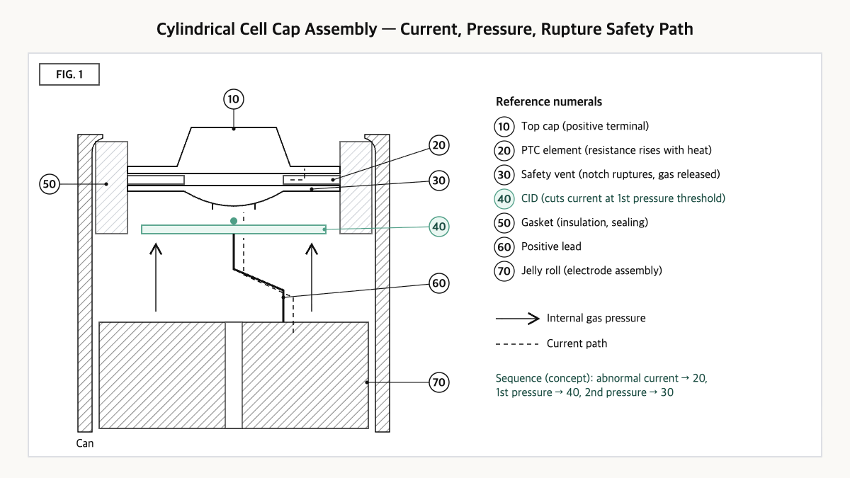
Source: reconstructed by the editorial team from Xu et al. (2021), Li et al. (2020), and the general configuration described in US8968898B2.
Follow the sequence of operation. When current becomes abnormally large, as in an external short, the PTC first raises its resistance through heating and limits the current. When gas is generated internally, for example by overcharge, and pressure rises, the CID welded beneath the vent separates at the first pressure threshold and cuts the current path. If the reaction still does not stop and pressure keeps rising, the notch (an intentionally thinned groove) engraved in the vent ruptures at the second threshold and releases gas to the outside. The CID and vent of an 18650 cap are described, respectively, as a device that ‘electrically isolates the cell upon internal pressure increase’ and one that ‘relieves internal pressure before case rupture’[2].
The key point is that the CID and the vent use the same ‘pressure’ signal in two stages. The current is cut first to reduce the reaction’s fuel supply, and only if that fails is the cell opened. If the gap between the two thresholds is narrow, the vent bursts as soon as the CID trips; if it is too wide, the can must withstand high pressure for a long time after the CID trips. This gap is the variable designers actually tune.
③ Comparison — Signal, Action, and Measured Values of the Three Devices
| Item | PTC thermistor | CID (current interrupt device) | Safety vent (top vent) |
|---|---|---|---|
| Trigger signal | Heat (temperature) from overcurrent | Internal pressure (1st threshold) | Internal pressure (2nd threshold) |
| Main hazard addressed | External short[3] | Overcharge[3] | Pressure relief before can rupture[2] |
| Presence in commercial 18650 | Optional (cases without it exist)[1] | Mandatory[1] | Mandatory[1] |
| Activation pressure, ambient (MTI / LG MJ1) | Not applicable | 1.058±0.053 MPa / 1.293±0.119 MPa[2] | 2.308±0.196 MPa / 2.202±0.083 MPa[2] |
| Activation pressure, 100°C | Not applicable | 0.920±0.076 MPa / 1.066±0.068 MPa[2] | 1.919±0.132 MPa / 1.866±0.084 MPa[2] |
| Activation pressure, 300°C | Not applicable | Not reported | 0.448 MPa / 0.400 MPa (mechanical simulation prediction)[2] |
Source: reconstructed by the editorial team from Xu et al. (2021)[1], Li et al. (2020)[2], and the NASA NESC Technical Bulletin (2009)[3].
What this table shows: At ambient temperature, the vent activation pressure is about 1.7–2.2 times that of the CID, so the two devices form a clear two-stage threshold. At 300°C, however, vent activation pressure is predicted by simulation to drop to 0.400–0.448 MPa, lower even than the ambient CID activation pressure, so in high-temperature scenarios the operating sequence assumed by an ambient-temperature design may not hold.
④ Patent Perspective — A Claim That ‘Removes’ the PTC and CID
Cap assembly patents are often read as adding devices, but an interesting example of how the scope of rights is drawn lies on the side of removing them. US8968898B2 (“Cap assembly of novel structure and cylindrical battery employed with the same”), filed by LG Chem and currently listing LG Energy Solution as assignee, is such a case. Its priority date is 2010-10-15, US filing date 2013-03-27, publication 2013-08-22 (US20130216871A1), and grant 2015-03-03; per Google Patents its legal status is Active (anticipated expiration 2031-10-11), with 10 claims. Listed family members include KR101279994B1, JP5593451B2, CN103155225B, and WO2012050343A2[4].
The technical gist of the abstract is a configuration that places a ‘safety element that interrupts current at a predetermined temperature’ between the safety vent and the electrode lead, so that no PTC element is required and the role of the conventional CID is also replaced[4]. Restating claim 1 element by element, rather than reproducing the original text, gives the following.
| Elements of claim 1 (restated) | Meaning for the scope of rights |
|---|---|
| (a) A cap assembly mounted at the open upper end of a cylindrical container housing a cathode/separator/anode jelly roll | Subject limitation — cap assembly of a cylindrical cell |
| (b) The electrode lead of the jelly roll is electrically connected to the lower end of a safety vent having notches that rupture to release gas under high pressure | Direct connection to the vent bottom — a connection structure that does not presuppose a separate CID plate |
| (c) A thermal fuse that interrupts current at a predetermined temperature is coupled to a region of the electrode lead | Specifies the safety element’s location as ‘on the lead’ |
| (d) The lead is bent at the front end of the fuse-coupled region so as to be directed outward from the center of the jelly roll, and is bent inward again at the rear end of the fuse-coupled region | The lead’s ‘outward, then inward again’ double-bend shape — the key limitation for infringement analysis |
Source: reconstructed by the editorial team from claim 1 of US8968898B2 on Google Patents (original claim language and drawings are not reproduced verbatim).
The scope of rights of this claim is narrowed not to the whole idea of ‘using a thermal fuse’ but to a configuration in which the fuse sits on the lead and that lead has a specific double-bend shape. The first point to compare when assessing the risk of infringement is therefore the bend shape in (d).
Design-around scenarios (with counterarguments): (i) placing the thermal fuse in an upper cap component rather than on the lead, (ii) securing the fuse region by bending the lead in only one direction, and (iii) retaining both the CID and PTC in the conventional way may fall outside the literal scope of claim 1. The counterargument is clear, however. Even if the shape differs slightly, a configuration that produces substantially the same function and effect as the double bend in (d) could be argued to fall within the range of equivalents. And even if (iii) avoids this patent, it may run into other rights on the CID and vent themselves, so a freedom to operate (FTO) review should cover the entire cap configuration, not just this one patent.
Cross-check of similar patents: EP2466668B1 from the same applicant (priority 2009-08-14, filed 2010-08-13, granted 2014-10-22, Active, anticipated expiration 2030-08-13) contains, conversely, a specification configuration that retains the CID and provides it with two or more through-holes for gas exhaust[5]. That ‘rights that refine the CID’ and ‘rights that replace the CID’ coexist within a single applicant shows that cap design is still open in several directions.
⑤ Limits and Outlook
On the optimistic side, designs that redistribute the roles of the devices in the cap (for example, removing the PTC or integrating a thermal fuse) could evolve in a direction that reduces part count and resistance, benefiting both cost and power.
There is also a counter-scenario. In-cell devices are ultimately designed around ‘one cell.’ In a pack with many cells connected in series and parallel, even if one cell’s CID trips, the voltage of the rest of the circuit may be applied across that cell, and, as the NASA bulletin notes, protection by in-cell devices is not always assured in high-voltage, high-capacity designs[3]. Add the simulation prediction that the vent threshold falls sharply at 300°C[2], and the ‘operating sequence’ inside the cap should be seen as a dynamic variable that changes with temperature.
The strategic alternative is to write down protection functions by layer. Summarizing on one sheet which layer — cell (CID, vent), module (fuses, busbars), or pack (BMS, breakers) — handles which signal makes visible how a decision to remove a device from the cell cap shifts the burden to the pack layer. This sheet also becomes the criterion for deciding ‘which layer’s rights to secure’ when building a patent portfolio.
Action to check (planning/IP teams): Confirm from the specification sheet the CID and vent activation pressures (ambient/high temperature) and whether a PTC is installed in your own or procured cells, and if the cap contains a thermal fuse or a bent-lead structure, compare it one-to-one against elements (b)–(d) of claim 1 of US8968898B2.
Items Requiring Verification
- Quantitative values for the PTC thermistor’s trip temperature and recovery characteristics could not be confirmed from sources in this article, so no figures are given.
- The claim 1 language of EP2466668B1 could not be fully extracted from the original. The description in the text is based on the configuration of the invention described in the specification.
- Whether the configuration of US8968898B2 has been applied to mass-produced cells, and the current legal status of the Korean counterpart (KR101279994B1), were not separately verified.
- The technical purpose stated in the specification for bending the lead twice in US8968898B2 (fuse protection, ease of assembly, etc.) was not examined in detail in this article.
- The activation pressures in Fig. 2 are values from a single study on two caps (MTI, LG MJ1) (measured at ambient and 100°C, simulation-predicted at 300°C) and cannot be generalized to other cells.
Sources
- B. Xu, L. Kong, G. Wen, M. G. Pecht, “Protection Devices in Commercial 18650 Lithium-Ion Batteries,” IEEE Access, vol. 9, pp. 66687-66695, 2021, DOI 10.1109/ACCESS.2021.3075972. Link
- W. Li, K. R. Crompton, C. Hacker, J. K. Ostanek, “Comparison of Current Interrupt Device and Vent Design for 18650 Format Lithium-ion Battery Caps,” Journal of Energy Storage, vol. 32, 101890, 2020, DOI 10.1016/j.est.2020.101890. Link
- J. Jeevarajan, “Limitations of Internal Protective Devices in High-Voltage/High-Capacity Batteries Using Lithium-Ion Cylindrical Commercial Cells,” NASA NESC Technical Bulletin No. 09-02, 2009. Link
- Google Patents, US8968898B2 “Cap assembly of novel structure and cylindrical battery employed with the same,” bibliographic data and claim 1 (original checked 2026-09-23). Link
- Google Patents, EP2466668B1 “Cylindrical rechargeable battery with improved stability,” bibliographic data (original checked 2026-09-23). Link
This article is a technology and patent trend commentary, not legal advice. Specific FTO judgments require professional review.
Related Reading