Coating an electrode more thickly packs more energy into the same volume, but as thickness grows, so does the capacity that cannot be used during high-rate charging and discharging. This article lays out the gains and costs of thick electrodes from first principles, and reads the claim boundary through 24M Technologies’ semi-solid electrode patent, which claims a thickness of 250–2,000µm.
① What’s the Topic
The gain from thick electrodes comes not from loading more active material but from using fewer inactive components such as current collectors and separators, and the price is paid in through-thickness ion transport.
Start with the industry context. There are two broad ways to raise cell energy density: raise the capacity of the materials themselves, or reduce the “useless volume” inside the cell with the same materials. The flagship of the latter is the thick electrode, that is, a high-loading electrode that carries a large amount of active material per unit area. According to a calculation in one review paper, in a cell stacking five layers of 25µm electrodes, the electrodes occupy 56% of the total volume, but using 200µm electrodes in the same volume raises that share to 88%[2]. As the number of current-collector and separator sheets falls, room for active material grows.
The tension grows with thickness. 24M Technologies’ patent specification states that conventional electrodes generally cannot be made thicker than about 100µm. Once single-sided coating thickness exceeds 100µm, through-thickness diffusion limitations such as porosity, tortuosity and impedance grow rapidly, significantly reducing rate capability, and cracking and delamination from the current collector tend to occur during drying[1]. Another review likewise summarizes that increasing thickness raises energy density but increases resistance, at the cost of power density[3].
The question this article answers is this: When an electrode is made thicker, what exactly is gained and what is lost, and where has a patent that tries to overcome the limit drawn its fence?
② Basic Principle — A Thick Electrode Is a “Deep Theater With Only One Entrance”
Think of the electrode as a theater and the lithium ions as the audience. The audience can enter only through the entrance on the separator side, and the seats stretch from the entrance all the way to the wall on the current-collector side. A thin electrode is a small theater, shallow from front to back, so the audience quickly fills every seat. A thick electrode is a deep auditorium. If people enter slowly (low-rate charging and discharging), every seat eventually fills, but if they are rushed in (high-rate charging and discharging), the seats near the entrance crowd first and the show begins with the inner seats still empty. Those empty seats are “the capacity not used at high rate.”
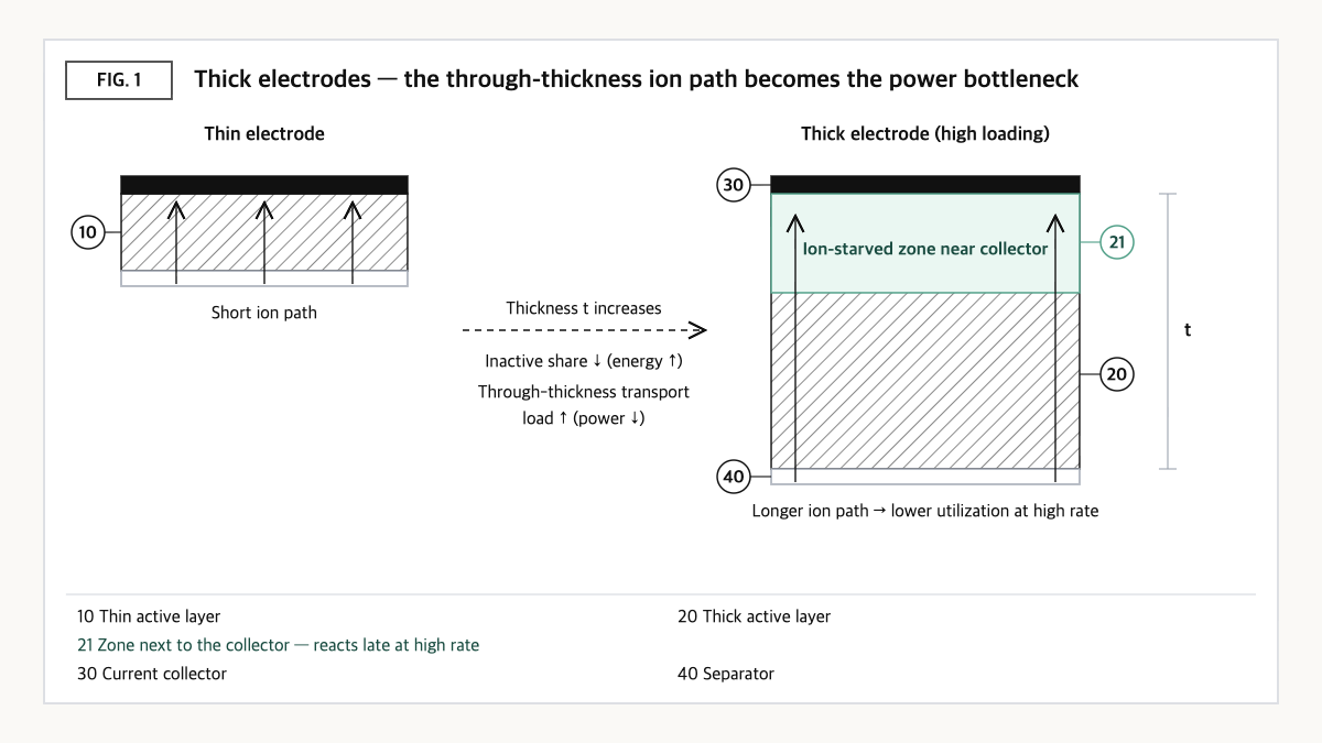
Source: reconstructed by the editorial team from the US8993159B2 specification and a thick-electrode review paper.
This is where the shape of the aisles matters. Ions travel through the electrolyte filling the pores inside the electrode, and if there are few pores (low porosity) or the pores are winding (high tortuosity), the actual travel distance becomes longer even at the same thickness. That is why the patent specification lists porosity, tortuosity and impedance together as through-thickness diffusion limitations[1]. Electrons, conversely, must travel through the solid network from the current collector to the active particles, so this path also lengthens as thickness grows.
There are manufacturing hurdles too. When a slurry is coated thickly and dried, rising temperature lifts the light conductive additive and binder toward the top of the electrode, a phenomenon called binder migration, which can weaken adhesion to the current collector and cause microcracks[2]. In short, the competition in thick electrodes is not about “how thick” but about “how evenly the electrode reacts, and how evenly it sets, through its thickness.”
③ Comparison — Thin Electrodes, Thick Coated Electrodes, and Semi-Solid Thick Electrodes
| Axis | Thin coated electrode (e.g., 25µm) | Thick coated electrode (over 100µm, e.g., 200µm) | Semi-solid thick electrode (US8993159B2) |
|---|---|---|---|
| Electrode share of cell volume | 56% (five-layer stack calculation example)[2] | 88% (same-volume calculation example)[2] | No sourced figure |
| Electrode thickness | 25µm | Conventional electrodes generally made at about 100µm or less[1] | Cathode thickness about 250–2,000µm (claim 1)[1] |
| Rate capability | Relatively favorable (qualitative) | Tends to drop significantly above 100µm due to diffusion limitations[1] | Area specific capacity of at least 7mAh/cm² at C/4 (claim 1)[1] |
| Manufacturing hurdles | Relatively small (qualitative) | Drying cracks, current-collector delamination, binder migration[1][2] | Active material suspended in liquid electrolyte — reads as a configuration that does not presuppose solvent drying |
| Active material composition | Conventional electrode compositions around 150–200mAh/g (specification background)[1] | Active material about 35–75vol%, conductive material about 1–8vol% (claim 1)[1] | |
Source: reconstructed by the editorial team from the US8993159B2 specification and claims[1] and the review by Sim et al. (2023)[2].
What this table shows: Thickening electrodes from 25µm to 200µm raises the electrode share of cell volume from 56% to 88%, but conventional coating hits a wall in power and manufacturing yield around 100µm. The semi-solid approach aims to get past that wall in the region above 250µm, and in exchange it has tied its scope of rights tightly to composition, thickness, area capacity and mixing state.
④ Patent Perspective — “How Well It Is Mixed,” More Than Thickness, Became the Fence
The key patent is US8993159B2 (title: Semi-solid electrodes having high rate capability) held by 24M Technologies. Its five inventors include Yet-Ming Chiang. Its priority date is 2012-12-13 (US provisional application), its filing date is 2013-04-29, it was published (US20140170524A1) on 2014-06-19 and granted on 2015-03-31, and its legal status on Google Patents is Active (anticipated expiration 2033-04-29), with 30 granted claims[1].
Two terms first. C-rate is a unit for charge and discharge speed: 1C is the current that uses the full cell capacity in one hour, and C/4 is the current that uses it in four hours. Area specific capacity is the capacity held by 1cm² of electrode (mAh/cm²) and is the representative metric for judging thick-electrode performance.
| Elements of claim 1 (restated) | Meaning for the scope of rights |
|---|---|
| (a) An electrochemical cell including an anode | Anode form is not limited |
| (b) A semi-solid cathode in which about 35–75vol% active material and about 1–8vol% conductive material are suspended in a non-aqueous liquid electrolyte | Limited by the electrode form “semi-solid suspension” and a composition window — an axis that distinguishes it from dried, binder-based coated electrodes |
| (c) An ion-permeable membrane between the anode and the semi-solid cathode | Ordinary configuration |
| (d) Semi-solid cathode thickness of about 250–2,000µm | Numerically limits the thick-electrode region |
| (e) Area specific capacity of at least 7mAh/cm² at C/4 | Limited by result (performance) — thickness alone without meeting performance falls outside |
| (f) Mixing index of the semi-solid cathode of about 0.8–0.975 | Key limitation — pins down numerically how evenly the suspension is mixed, so even with the same composition, coverage depends on process quality |
Source: reconstructed by the editorial team from the claim structure of US8993159B2 (original claim wording and drawings not reproduced verbatim).
A point worth noting is the difference between the abstract and claim 1. The abstract mentions a thickness of about 250–2,500µm and at least 5mAh/cm² at C/2[1], whereas granted claim 1 lowers the thickness ceiling to 2,000µm, changes the performance condition to C/4 and 7mAh/cm², and adds a process-quality index, the mixing index. It is a textbook case showing that judging the scope of rights from the abstract alone risks reading it broader than it is.
Design-around scenario (with counterargument): On a literal reading, the clearest design-around axis is the electrode form in (b). An ordinary coated electrode set with binder and dried is likely not to meet the element of “a suspension in liquid electrolyte.” Even with a semi-solid approach, keeping thickness below 250µm, adding more than 8vol% conductive material, or having a mixing index outside the range could fall outside the literal scope of claim 1. There is a counterargument. The claim attaches “about” to each number, keeping the boundaries loose, and the same family continues with later patents including US9184464B2, US9362583B2, US9385392B2, US9831518B2, US9831519B2, US10483582B2, US11018365B2 and US11811119B2[1], so it is hard to rule out that a design avoiding claim 1 is caught by a different combination in another patent. Whether the mixing index is met can also only be gauged by reproducing the measurement method as defined in the specification.
Cross-check of similar patents: The same family also extends to Japan (JP6698349B2), Europe (EP2932542B1) and the PCT (WO2014093876A1)[1]. Another route to thick electrodes is the dry electrode, made by pressing powder without solvent; a compression-ratio patent in this line (SK On’s US12199265B2) holds its rights on a process axis entirely different from semi-solid, so direct overlap between them appears unlikely.
⑤ Limits and Outlook
On the optimistic side, thickening electrodes to reduce the share of current collectors and separators is one of the few ways to improve energy density and cost at the same time without changing materials. The calculation showing the electrode volume share rising from 56% to 88% as thickness increases from 25µm to 200µm[2] illustrates the potential of this direction well.
The counter-scenario is also clear. If electric-vehicle market demand shifts from “go farther” to “charge faster,” thick electrodes, whose bottleneck is through-thickness ion transport, become a disadvantage. The energy density gained by thickening may be offset by lower utilization under fast-charging conditions and by charging-current limits imposed to prevent lithium plating.
The strategic alternative is to design the through-thickness structure together when increasing thickness. Typical approaches include creating pore channels that ions pass straight through, or splitting the composition between the separator side and the current-collector side. This leaves room to reduce power loss while keeping the energy gain of thick electrodes, and on the IP side it allows the portfolio to expand into structural claims, beyond the narrow arena of fighting over “thickness numbers” alone.
Action to check (planning/IP teams): If any project in your thick-electrode roadmap is evaluating a semi-solid or suspension approach, compare four items — thickness, conductive content, area capacity at C/4, and mixing index — one-to-one with US8993159B2 claim 1, and tabulate the independent claims of the eight later patents in the same family alongside it.
Items Requiring Verification
- The definition and measurement procedure of the “mixing index” in the US8993159B2 specification were not reviewed in detail this time.
- The claims and legal status of each of the eight later patents in the same family were not individually checked.
- No figures were obtained for the electrode share of cell volume in semi-solid thick electrodes, or for energy density (Wh/kg) at the level of mass-produced cells.
- The outlook that “fast-charging demand works against thick electrodes” is a reasoning from principles and was not verified with market data.
Sources
- Google Patents, US8993159B2 “Semi-solid electrodes having high rate capability,” bibliographic data, specification and claim 1 (original checked 2026-09-23). Link
- Yoon Bo Sim, Bo Keun Park, Ki Jae Kim, “Reasonable design of thick electrodes in lithium-ion batteries,” Frontiers in Batteries and Electrochemistry, 2023. Link
- Jiashen Chen et al., “Modelling of lithium-ion battery electrode calendering: A critical review,” Journal of Energy Storage, 2025. Link
This article is a technology and patent trend commentary, not legal advice. Specific FTO judgments require professional review.
Related Reading
- SK On’s Dry-Electrode Compression-Ratio Patent (US12199265B2) — The Narrow Window for Crack-Free Roll-to-Roll Calendering
- Dry Electrodes: Remove the Solvent and the Binder Becomes the Bottleneck — The Material Constraint of PTFE Fibrillation
- [Patent Analysis] LG Energy Solution’s Dual Slot-Die Coater Patent (US20250375790A1) — The Scope of Rights Opened by Simultaneous Double-Layer Coating Through a Die-Lip Thickness Differential